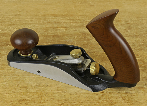
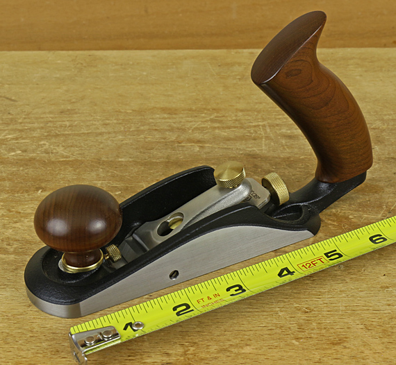
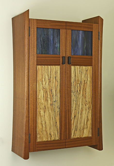
[32″h x 20″w x 8″d] The curved sides of this cabinet started on the bandsaw, of course, but then I used the #20 compass plane, the RP rasp, and scrapers. The best tool for final truing of the curves was a simple purpose-built sanding shave. This is just a 14″-long stick, about 1″ x 2″, with the working wide face planed a bit convex, to which is attached PSA sandpaper.
With all the tools on which we spend a small fortune, almost every project necessitates a shop-made tool to save the day.
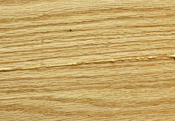
The dowel joinery went well. I have plenty of experience with it. Well, except for one section where I used too much glue and paid the price correcting a squeeze-out mess. Think! It is so much easier to avoid than to correct mistakes.
Just clamp the carcase together, right? No. The curved sides required specially shaped clamp blocks. It was so easy to draw that nice curve on paper . . .
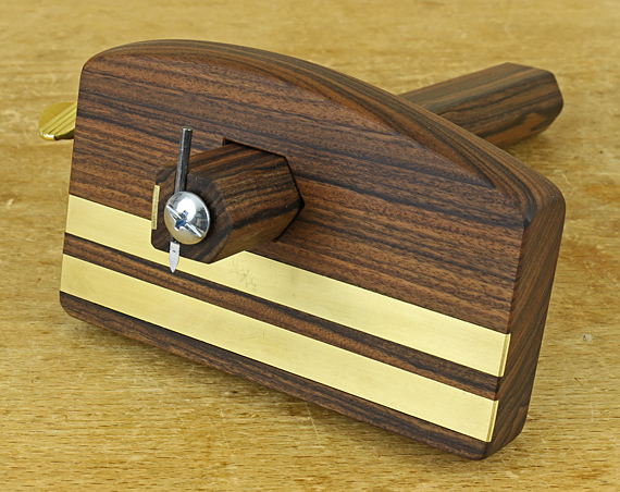
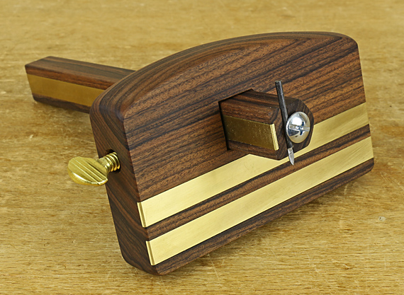
For the door frame joints, I choose regular mortise-and-tenons rather than slip joints, which look cool but are a major pain to clamp. I routed the mortises and then carefully set up the bandsaw to make the tenons within a shaving or two (or none) with the rabbet block plane. It’s all about making a precise kerf-width-thick gauge.
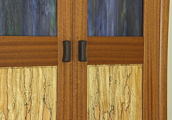
There’s a limit to masochism, or maybe not. The unconventional arrangement of the door frame rails and stiles made the final fitting of the doors more difficult. This was, however, a key design element of the piece so it was worth the trouble. The step at the junctions of the inner rail and stile on each door was another pain. A bigger pain would have been to try to assemble the door pieces in the wrong (impossible) order.
After a lot of mulling over, I decided to use magnetic catches. I should have embedded the fixed magnets in the fixed shelf but I made a separate little block for them, which could be removed and replaced if everything did not work out. The catches work nicely but I should not have chickened out on the design.
See the convex front edge of the sides? That feature made everything more difficult, especially the final fit of the doors. Does it matter? Yea, I think so; I like the look. It’s just a matter of deciding if it is worth it.
The problem with one-of-a-kind work is that you never experience all the issues and see the end point until you’re done. Yes, I would have done some things differently if I were to make this again. But I’m not going to.
The top panels are opalescent art glass. I learned a lot about art glass and glass cutting tools and techniques for this project. I installed the glass with strips that are screwed in place, not nailed as Krenov did.
From the start, I planned to use Z-clips to hang the cabinet. These are essentially metal French cleat hangers but take up only 1/4″ of depth in the back of the cabinet. They must be accounted for when forming the rabbet for the back panel, including some consideration for walls not being perfectly flat.
Virtually every project requires learning about a new material, technique, finish, or design element. I enjoy that.
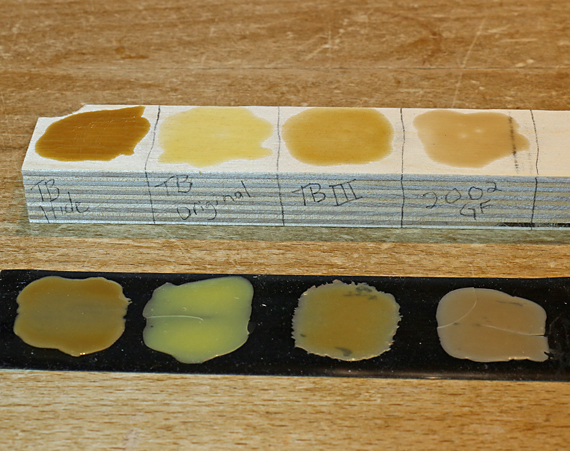
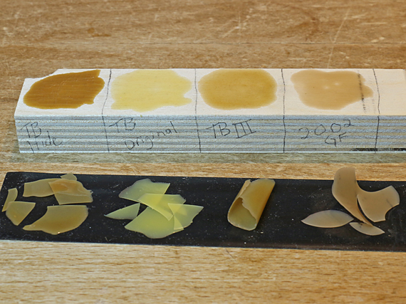
The spalted big-leaf maple panels were a nice find, and they bookmatched well for spalted wood. Like most well spalted material, there were some soft areas that needed hardening. Protective Coatings PC-Petrifier works well with minimal darkening.
For the hinges, bright or even brushed brass just would not look right, and the antiquing on the hinges that I bought proved to be delicate, so I blackened them for good with a solution from Rockler.
I could go through a dozen or more other special issues with this piece but you get the idea. The truth is that there is a lot of thought, time, trouble, and – is suffering too strong a word? – in making these things.
Are these details worth it? How about the specialized tools, finding the right wood, correcting mistakes, refining the design (over and over), finding the way out of construction problems, and on and on?
Only the maker can answer these questions. That’s the privilege – and the joy – that comes with making things. Best wishes for you and your projects.