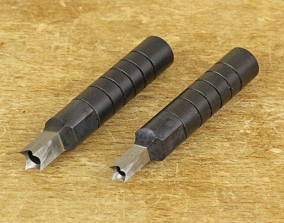
The otherwise excellent square hole punches from Lee Valley have a practical problem that I detailed on this blog more than two years ago, along with a suggested solution.
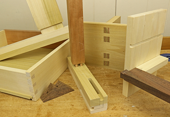
In brief, the punches work beautifully to square the upper section of a round hole in applications such as a pegged mortise and tenon joint. The punches are sized from 3/16″ to 1/2″ in 1/16″ increments. Each requires boring a round hole 3/64″ less than the width of the punch and thus the use of unusually sized dowel pegs.
For example, a 13/64″ hole is used with the 1/4″ punch. After forming the square portion, the round hole could reasonably be enlarged to 7/32″ but anything further would risk damaging the edges of the square. So, here’s the problem: how to obtain round pegs in diameters such as 13/64″, 7/32″, and so forth. Even Lee Valley, despite my suggestion, does not supply the equipment to make such dowels.
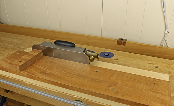
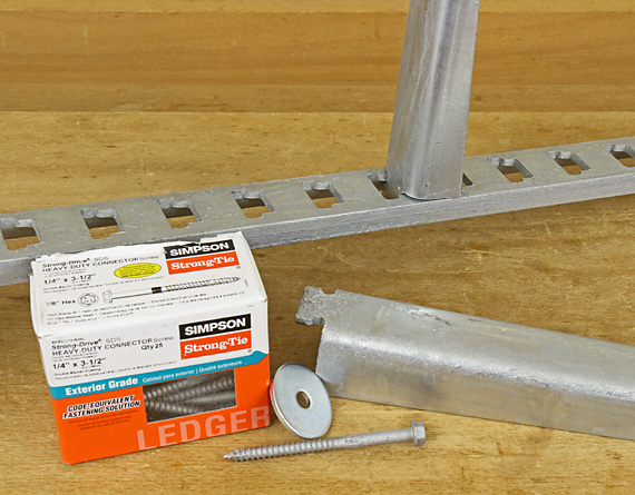
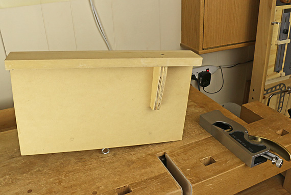
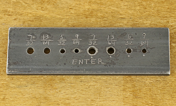
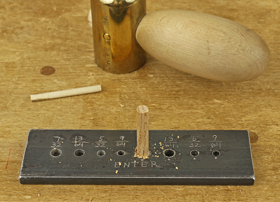
There are methods demonstrated on the internet for making dowels using a portable power drill and clever shop-made cutters, but I prefer a simple dowel-former plate to make these short pegs. This is easily made from a piece of unhardened weldable steel, 1/4″ x 1 1/2″ x 5″, from the local hardware store. Rough-shaped stock is pounded through the holes to form the dowels.
Construction
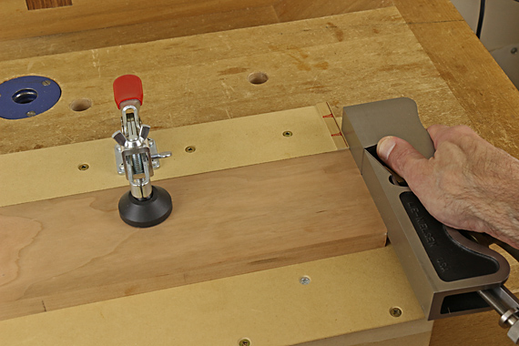
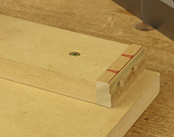
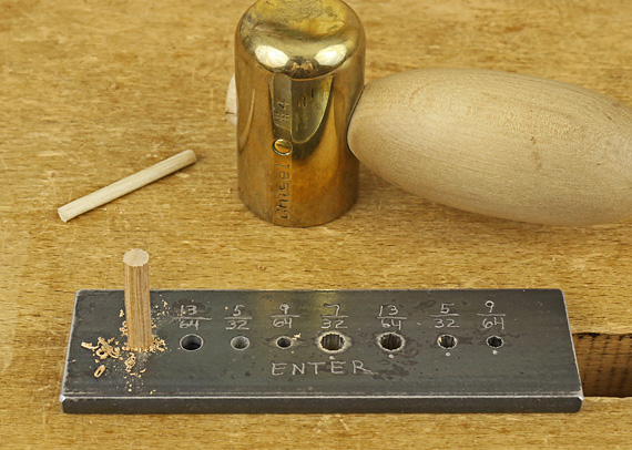
Use a drill press to bore two holes for each diameter, one for rough cutting and the other for finish cutting. The roughing holes are on the right side of the plate in the photo at top. Relieve the diameter of all holes by reaming from the exit end using a General #130 6° tapered reamer, going to full depth for the roughing holes and about 1/2 depth for the finishing holes.
Deeply score the sidewalls of the roughing holes with a 2/0 blade in a fret saw and a 4″ double extra slim saw file. Use a small sharpening stone to cleanly remove the burr and create a sharp edge on the entry side of the holes. Use a countersink bit to lightly chamfer only the exit side of all holes.
Use
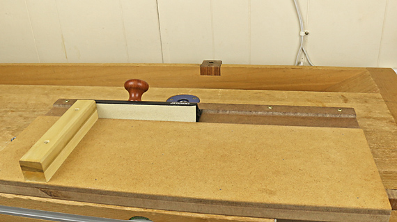
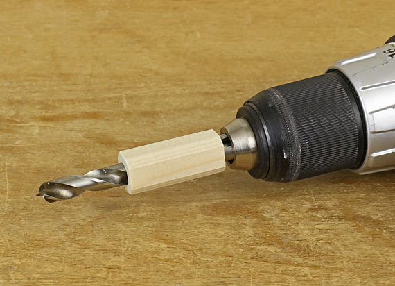
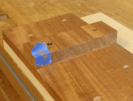
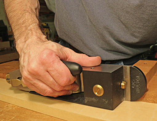
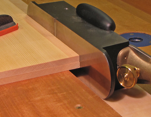
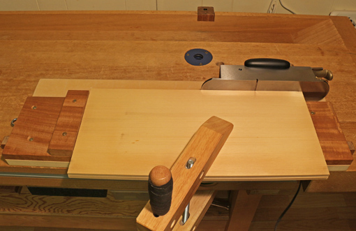
Start by making stock from straight-grained wood, ideally riven, to a width slightly more than 1/64″ larger than the hole diameter. Trim the corners to make an approximately octagonal cross section. I prefer to use a small handplane for this step.
Directions for using this type of plate usually recommend whittling an approximate taper on the blank to ease its entry into the hole. However, I’ve found the forming cutting goes much smoother and more balanced with a nicely centered blunt entry point formed on the blank with a pencil sharpener or dowel pointer.
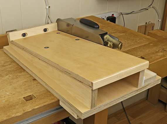
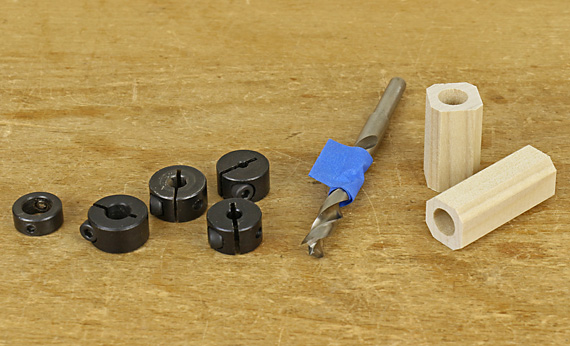
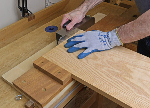
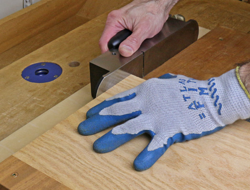
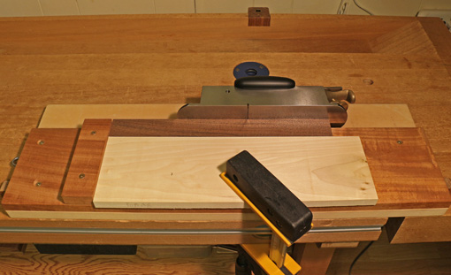
Place the former hole over a dog hole in the workbench top. Use the roughing hole first, followed by the finishing hole. Pound the wood blank with a mallet, taking care to keep the blank perpendicular. Proceed until the blank is nearly flush with the plate, then use a narrower peg to tap it the rest of the way though. A piece of blue tape under the dog hole will catch the dowel, saving the frustration of looking for it on the floor.
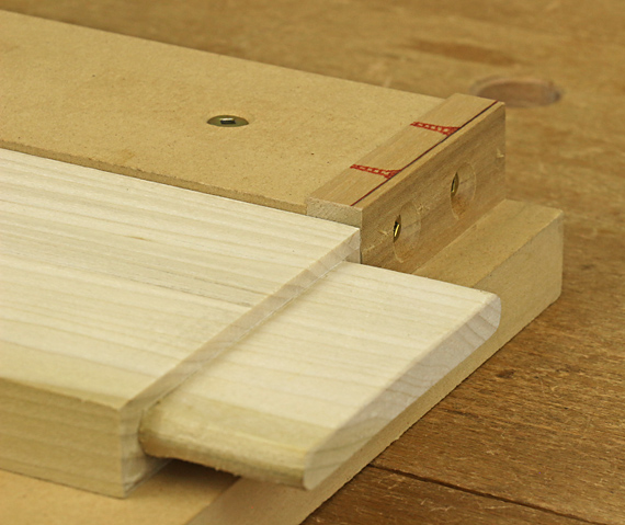
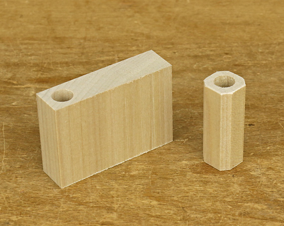
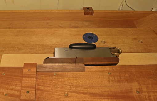
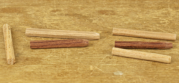
I have found that the two-stage process produces smoother cutting and better dowels. The photo below shows, from left to right, a piece of shaped stock, rough dowels formed by the first step, and straight, smooth finished dowels in cherry, bubinga, and red oak.
Ideally, this tool would be made of hardened tool steel like a genuine Veritas or Lie-Nielsen but that is beyond what I can accomplish in my shop. However, the shop-made version is inexpensive, easy to make, has any hole size you want, solves the problem with the square chisels, and works surprisingly well.