Archive for the Category ◊ Techniques ◊

Author:
• Friday, April 24th, 2020
dovetail markout

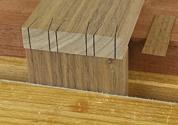
In writings from the 1970s and 80s, Charles Hayward, Ernest Scott and others discuss using shallow saw kerfs to mark the tail layout onto the endgrain of the pin board. The idea is to drag the saw through the tail kerfs, which act as guides. There is no instruction to laterally displace the tail board to compensate for the width of the kerf, and so the intention is to saw to one side of the mark.

I find it difficult to start the cut by following such a mark. Moreover, if the start of the cut is imperfect, it is too easy to become disoriented by the hacked up endgrain surface. I do not like or use this method. 

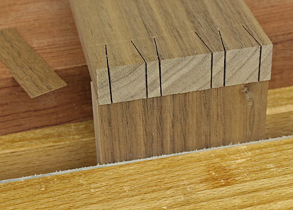
A better method is to use shallow kerfs to guide the placement and engage the saw as you start to saw the pins. Of course, you must laterally displace the pin board to compensate for the kerf thickness. Otherwise, the sockets will be too wide by the amount of two kerf widths. 

I do not know who first came up with this method. I first saw it on Kevin Drake’s website. More recently, dovetail master Rob Cosman, who mentions that he learned it from The Encyclopedia of Furniture Making by Ernest Joyce, has taught it. I suspect that like most woodworking methods, it has been around longer than we realize. 

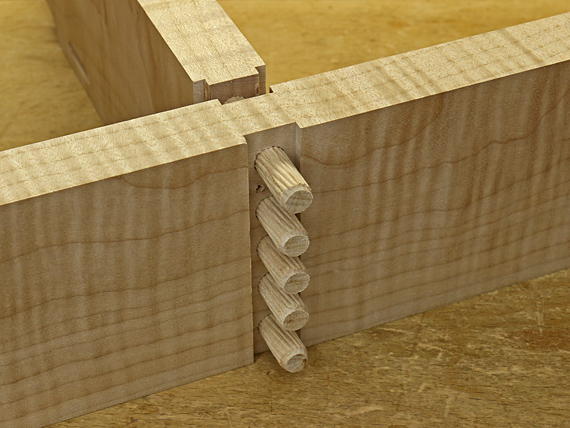
In the demonstration photo above, the tail board is shifted one kerf width to the left to prepare for making marks through the kerfs on the right side of the tails. This puts the kerf marks in the waste wood of the sockets on the pin board.

Below, the tail board is shifted to the right for making the marks through the kerfs on the left side of the tails.

dovetail mark out

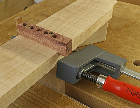
To gauge the shift, I used a shim that is a tight fit in a kerf made by my dovetail saw. You can regulate the tightness of the joint and/or allow for a margin for error by adjusting the thickness of the shim. Making a slightly thicker shim (say .002″ or a piece of Scotch tape) will make the sockets slightly undersized. This may be good for softer, more compressible woods. 

Make the kerf marks before sawing or chopping out the waste between the tails. This gives you a tighter guide. Note that you have to saw the tails square or at least to a one-sided tolerance.  

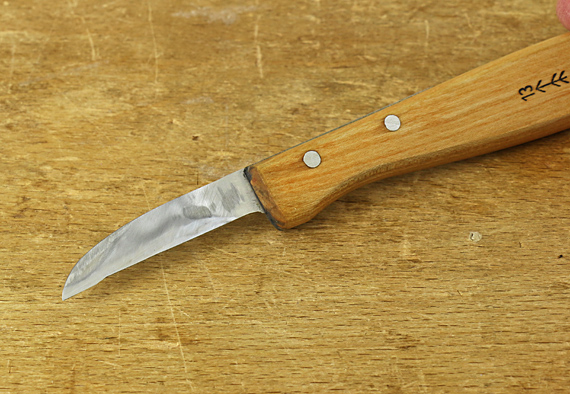
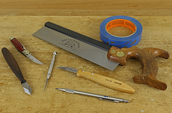
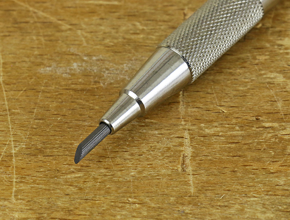
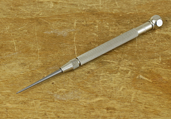
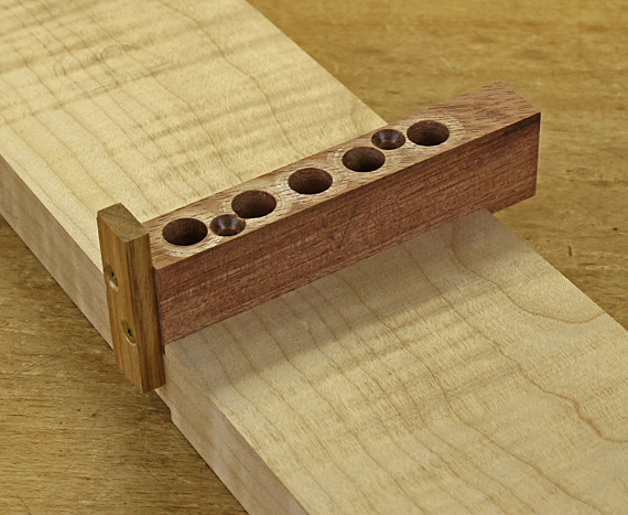
You will need a specialized tool to make the kerf marks. With a Western saw, it is impossible to make them on the push stroke, and slow going on the pull stroke unless the wood is quite soft. Japanese saws do not work well for this because the teeth do not extend to the toe of the blade. 

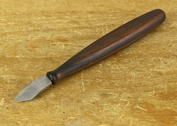
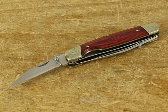
Kevin Drake’s system uses a hawk bill scraper, which acts as a saw with a single big tooth, while Rob Cosman sells a nifty marking tool that is essentially a tiny pull-stroke saw with the same kerf width as his dovetail saw. Note that Drake’s system uses a special dovetail saw with no teeth at all at the toe to aid in registering the saw in the kerf mark. 

Unlike when using a scriber or knife, it is easy to inadvertently shift the tail board when making these pronounced marks in the pin board endgrain. A dovetail alignment board of the sort used by David Barron is one way to minimize this. This tool is a great aid to dovetailing no matter the transfer method you use.  

Another method, is to make a very shallow rabbet (1/32″ is enough) on the inside face of the tail board. This gives a dead-on, steady alignment of the tail board against the pin board. I really like this trick for dovetailing in general and use it especially for wider boards. I recall first learning it from an article by Rob Cosman in Popular Woodworking (April 2006), where he notes that he learned it from Ian Kirby. 

Remember, any method of marking out the pin board goes better if you are working on cleanly sliced endgrain, at least from the table saw or, better, from the shooting board.

So, there you have it: three posts on the critical step of transferring the tail layout to the pin board. I suggest experiment and choose what works for you! My go-to method is still the scriber. I cut my first dovetails 40 years ago but I still like to explore and refine different methods. I’ve only experimented with the kerf mark method, but I may adopt it for some circumstances. I like having options as various woods and constructions favor different methods.

Category: Techniques  | Tags:  | 2 Comments
Author:
• Monday, April 06th, 2020
V point marking knife

Continuing the topic of transferring the layout of the sawn tails to the endgrain of the pin board, the purpose of these posts is not to argue for the superiority of any one method but rather to array the options to help you choose what works best for you and the specific project at hand. I vary my method depending on the species of wood, the type of dovetail (e.g. through or half-blind), and the thickness of the wood. 

V-point knives seem to be popular for this task, especially thin models that can slip in between narrowly spaced tails, such as the beauty made by Blue Spruce. Without a doubt, many highly skilled woodworkers produce excellent results with these tools, but I find it difficult to see the knife line. 

I do not mean that it is difficult to see the fine knife line at first, but when I start sawing across the endgrain, I cannot visually keep track of that skinny line to confidently split it with the saw. Chalking the endgrain is not much help. The scriber makes a V-groove that I can track and split better while sawing, and furthermore allows me to better see how I’ve done afterwards. I also find that a V-knife sometimes catches the side grain of the tail, slicing off a hair of it and slightly dislocating the layout line, albeit in the safe direction. 

Ian Kirby, one of my all-time favorite woodworking teachers, has favored a pocket knife for this task. This is not my preference but again, it is another option to consider. The sheepfoot in your three-blade stockman or a Wharncliffe blade like in this lovely Kershaw would be good choices for this because it is easy to reach the tip all the way out to the base of the tail.

Kershaw knife

One knife that I sometimes use is my modification of a Pfeil #13 chip carving knife. I removed the edge and a bit of the width from all but the first 1/4″ of the blade. I also ground the sides to a nearly flat single bevel. (The Pfeil #3 knife would probably also work.) I find this modified tool very easily reaches to the base of the tail and follows the wall of the tail with very little tendency to slice into it. So, I like it better than a V knife but I still usually have the dilemma of following a pretty fine knife line. 

modified Pfeil #13

What about the roll of blue tape in the photo in the previous post? Mike Pekovich, Creative Director of Fine Woodworking magazine, and a very skilled and thoughtful craftsman, covers the endgrain of the pin board with blue tape. (FW #240) He then knifes the tail outlines into the tape, removes the tape over the waste wood, and saws just adjacent to the remaining pieces of tape, which represent the pins. Clever!

I experimented with Mike’s method. It surely has merit, and some will love it, but I am not comfortable with it. The pieces of remaining tape can move, especially if you knick them while engaging the saw, and when they do move, I’m lost. I also do not feel comfortable with a piece of tape determining the registration of the saw. But give it a try, you might like it. 

Next: using saw kerfs as layout.

Category: Techniques  | Tags:  | 4 Comments
Author:
• Tuesday, March 31st, 2020
dovetail transfer tools

A critical step in hand-cut dovetailing is accurately marking out the second piece – usually the pin board – from the completed first piece – usually the tailboard. 

Sure, to make a good dovetail joint, you have to be able to reliably saw to a line and chisel to a line. You also have to understand the mechanics of the joint to appreciate how to tweak the contact surfaces and where you have a bit of tolerance and where you don’t. But if the transfer step is inaccurate, it’s all a losing battle.

So, let’s look at several options

Keep in mind that all of this depends on several variables including pin width, the texture of the wood, and your personal eyesight, lighting, type of saw, and technique. An effective marking out in cherry using a ripcut dozuki may be difficult in red oak using a Western backsaw. 

chisel point drafting pencil

A plain old pencil seems too crude for the precision required in dovetailing and yet it can work well for some. All of the pencil mark is in the keeper wood, so you have to saw to one side of it without touching it at all. A very clean, consistent line gives the best chance for success. A 2mm drafting lead sharpened on 320-grit sandpaper to a chisel point (above) can produce an almost knife-quality line, especially with 2H lead on a diffuse-porous wood like cherry. That said, a pencil is not my preference. 

Starrett scriber

I’ve used a scriber more than anything else for this job, perhaps because that is what I used long ago while learning (first learning, that is). I prefer the type of point on the Starrett scriber (above), which ends in a small, straight conical taper. Unlike a gradual curved taper, I can clearly tell when the scriber is or is not up against the wall of the tail wood. 

Used properly, the scriber point hugs the wall of the tail wood as it bites into the endgrain of the pin board, without any chance of it cutting into the side grain of the tail as a knife might. Thus, the bottom of the tiny V groove created by the scribe point is exactly under the tail wood wall. 

This works best if the sawn (and possibly pared) surface of the tail is straight and clean. Otherwise, the scribed line will be not straight and therefore probably confusing to follow with the saw.  

I have found the scriber effective in ring porous woods like red oak as well as fine, diffuse-porous woods like pear. The downside is the scribed line is not quite as clean and fine as a knife line. 

Next: a look at different marking knives and more.

By the way, go here for my free 42-page Dovetail Instruction Guide that I wrote several years ago for Craftsy. It really gets down to the sawdust and shavings to lead you to success. 

Category: Techniques  | Tags:  | 2 Comments
Author:
• Sunday, February 23rd, 2020
levelling table legs

In theory, the bottom tips of all four legs of a table should be in the same plane so it can sit on a flat floor without wobbling. Remember, however, the words of Yogi Berra, “In theory, there is no difference between theory and practice. In practice, there is.”

Now, if you made uniform leg lengths and mortise-and-tenon positions, you should have a flat base after assembly that requires no adjustment but stealth gremlins almost always prevent such perfection. 

On the other hand, consider that rarely is a floor flat over the area on which the table stands, so making the four legs true is really just playing the odds. Furthermore, a table, especially a large one, may flex when you place it on the floor to produce an automatic correction. The same goes for chairs. Therefore, all of this is often of no concern at all – in practice. 

For a small table though, this issue may be a significant concern. The small area of floor on which it stands may indeed be flat, the table may not flex much, and it feels creepy when it wobbles a lot. So, let’s look at how to assess this. 

It is best to do this with the top attached in its final configuration, which contains any flex in the frame induced by the top piece.

The simplest method is to put the small table on a true flat surface such as the table saw. If such as surface is not available, you can turn the table upside down and use winding sticks on the tips of the legs. Note that this may introduce error if the frame of a larger table flexes a bit differently than when it is right side up. In any case, for a larger table, I do not go hunting for a very flat floor, which probably does not exist; I just do not worry about the whole matter.

For small tables, I do like to get it pretty close. You can take off the error from the one long leg, as determined by how the table pivots on the flat reference surface, but I prefer to take off half that amount from each of the two long legs.

OK, if you have done everything just right in the shop and now place the table on the floor where it will live, which is not likely to be flat, and it wobbles enough to be annoying, what do you do? Shim it. A layer or two or more of tape such as duct tape is just fine – in theory and in practice.

Category: Techniques  | 4 Comments
Author:
• Saturday, January 18th, 2020
cross-rail joint finished

Dry fit the joint with just two dowels. Using all five dowels makes it remarkably difficult to disassemble. However, check every one of the long grain holes to make sure it is full depth so you don’t get a surprise when finally closing the glued-up joint.

I find it less stressful to glue up in two stages. I apply glue in the holes, and then tap in the dowels in one of the tongued components. I limit the depth of the dowels with a registration block. When this subassembly has dried enough to keep the dowels stable, I complete the glue up by applying glue to the other set of holes, plus a little bit on the dadoed piece, and then push the whole thing together. 

This joint must be clamped from the ends. I have found it strongly tends to stay accurately square but, of course, I check it anyway, and adjust the clamps as needed.

When the glue is dried and conditioned, I plane flush the outer edges. If made accurately, which is very likely if the dowel jig was made accurately, this joint will turn out neat and strong, and it will stay that way.

Much of the work in making this joint is in making the dowel jig, which is reusable for a joint of the same or less width. The joint also works with large width rails because there is no conflict from dimensional change due to moisture cycling.

This has been a good joint to have in my repertoire. You might want to give it a try.

Category: Techniques  | Tags:  | 2 Comments
Author:
• Monday, January 13th, 2020
drilling setup for cross-rail joint

Drilling the holes for the cross-rail joint is easy as long as you keep track of reference points and orientations.

First, attach the jig to the first side of the joint. Use the reference cleat to set the jig in place in the dado, and clamp it there. Pass a snug fitting transfer punch or brad-point drill bit through the fixation holes to make dimples in the floor of the dado. This creates reliable centered marks to drill minimal-depth pilot holes for the screws. Screw in the fixation screws, which only project about 1/4″ into the workpiece, and then remove the clamps.

With the jig now securely in place in the dado, you can prepare to drill the dowel holes. I have found no good way to accurately secure the jig onto the end of the tongued piece, so it is best to insert and clamp the tongued piece in the dado on the opposite side of the dowel jig in the orientation it will be when the joint is assembled. Thus, the holes will be drilled, guided by the jig, through the dadoed piece and into the tongued piece, all in one step.

The photo above shows the setup in the vise. Note the support block that helps keep the components at 90°. 

For drilling the holes in the joint, I use a hand-held electric drill and a DeWalt Pilot Point bit. Well made, its diameter is a good match to the high quality brad-point bit that I used to make clean holes across the grain in the jig. The DeWalt produces a little tearout drilling cross grain in the dadoed piece but that will not be seen and does not matter structurally. More important, it advances strongly through the long grain of the tongued piece, where a brad-point bit (essentially a cross-cut device) tends to bog down and burn. 

A good drill stop is a must for this work. I do not like any commercially available stops, and so I use shop-made stops (described here), which have never let me down. When working out the drilling depth, remember to take into account the jig and the dadoed workpiece. I drill 1/16″ – 1/8″ extra deep into the tongued piece to allow for excess glue. 

This is the joint so far:

cross-rail joint

Once you have finished drilling from the first side of the joint, detach the jig and reattach it to the dado on the “second” side of the joint. The cleat stays against the same edge of the dadoed piece but the opposite drilled face of the jig sits on the floor of the dado on the second side. The second tongued piece is set into proper orientation in its dado and the setup is clamped and registered the same as for the first side of the joint. 

For this second round of drilling, the holes in the dadoed piece already exist, so you are just going through them directly into the long grain of the tongued piece.

Here is a reminder of what we are trying to produce:

cross-rail joint

This is more difficult to describe than to do. This method ensures that all the components are drilled in the actual position they will be in the final joint. And that is why the dowel jig is made to be useable from both sides. 

Next: assembly and completion.

Category: Techniques  | Tags:  | 2 Comments
Author:
• Sunday, January 12th, 2020
dowel jig for cross-rail joint

The dowel jig for this joint is simple but it must be accurate. Use a fine-grained, very hard wood. I used some of my old stock of bubinga, one inch thick. The width of the jig must fit snugly into the dado, 5/8″ in this case. A little extra length helps in handling the jig.  

Make sure: all faces are flat and straight, the width and thickness are uniform over the full length, and adjacent faces are dead square to each other. Most woodworkers will use a table saw to make this little block of wood, as I did. Please be cautious working such little pieces, and make use of an appropriate work handling device. I like the GRR-Ripper for such work. It’s worth it. 

Use a good brad-point bit to drill the 3/8″ holes. The drill press must be set up to drill true at 90° because the jig will be used from both drilled faces. If the holes or the body of the jig is out of square, the joint will be inaccurate and difficult or impossible to assemble. 

The spacing of the holes is not critical but leave enough room for pass holes, countersunk at both ends, for two #6 x 1 1/4″ fixation screws. Attach a cleat with little screws at the end of the jig. It extends about 3/8″ beyond each drilled face, and will reference it to the edge of the workpiece. 

This is how the dowel jig will sit in the dado:

dowel jig for cross-rail joint

Next: using the jig.

Category: Techniques  | Tags:  | Comments off
Author:
• Wednesday, January 01st, 2020
cross-rail joint

Here’s how to make the joint described in the previous post.

The joint starts with back-to-back dados. These must be precisely aligned because the dowels that extend across the joint will afford virtually no wiggle room when the tongues enter the dados. I didn’t take a photo of the dados before I drilled the holes but you get the idea.

For the 7/8″-thick stock used here, the dados are 5/8″ wide and 1/8″ deep. This leaves a 5/8″-thick web through which the holes will be drilled. Since the 3/8″-diameter dowels are 2″ long, there will be 11/16″ of dowel length to penetrate the long grain of each of the two tongued components.

For a 1/2″ dado, I would use 5/16″-diameter dowels to leave enough meat around the dowels in the tongued components. 

How you make the dados is up to you, but accurate stock preparation is important for all methods. Handwork is doable: knife the lines, square them around to the other side, saw, chop the waste, pare the walls, and router plane the floor.

For machine methods you will be referencing from both long edges, so they must be exactly parallel. I used a 5/8″ downshear router bit, and a sled to move the work across my router table. A dado blade in the table saw would also work.

I used the same router bit and the router table to make the tongue in the other two components, sneaking up on the length and width to get a tight fit. If you make the tongue too long, or later reduce the depth of the dado with finish planing, it is easy to correct this by shooting off the excess tongue length. Just make sure the tongues are not too long (it’s a one-sided tolerance), which would prevent the shoulders from meeting neatly. 

So, now that we have the double dado joint, we are going to bind the whole thing together with dowels. Note that the glue surfaces in the tongued components are long grain-to-long grain. That, plus the multiple mechanical locks make this a very strong joint. Here is “half” of the joint:

cross-rail joint

Next: Making and using a simple dowel jig to make precisely aligned holes in all the components.

Category: Techniques  | Tags:  | 2 Comments