Archive for the Category ◊ Jigs and Fixtures ◊

Author:
• Sunday, January 15th, 2012

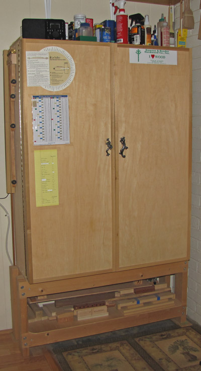
When I built this tool cabinet 25 years ago, I did not expect it to last this long. You know how it is: “I’ll just build something plain and practical now and make something nicer sometime later.” It was a time of stress and joy with a new family in a new house, and, of course, a new shop. My previous systems of tool storage using chests, shelves, cabinets, and even a closet, needed an upgrade and I wanted to make it quickly.

Well, “sometime later” has come and gone, and this old dog is still doing its job well. It is not perfect (what is?) but I feel no need to build a new one. In this series of posts (not necessarily contiguous), I will discuss the construction and features of the cabinet and why it works for me. Though a few readers may want to make one just like it, more likely this discussion will be a source for ideas to incorporate into your own designs for tool storage. I used ideas, many from sources I’ve long forgotten, plus some of my own, for this cabinet, for which I make no pretense of originality.

The overall design – a cabinet with two large, deep doors, standing on a low frame – allows a wide-open presentation of my hand tools. When I open those doors, it’s time to work. The great majority of tools can be reached directly, with little or no bending, and without shifting other tools out of the way. Being right-handed, I placed the cabinet immediately to the right of the workbench, giving me quick physical and mental access to the tools. In a small footprint of about 4 feet by 14 inches, a remarkable quantity of tools is stored.

There are many good ways to store hand tools. Everyone is entitled to his preference, but personally, I do not care for dandified tool wall cabinets or dovetailed chests that sit on the floor.

Here we go. The overall dimensions are 48″ high by 37″ wide by 14″ deep. The inside of the cabinet case has a depth of 11 1/4″. It contains three adjustable shelves and an 11″ high drawer bank with six drawers. Four drawers have inside depths of 2 ½”, and two have 3 ½”. The doors have an inside usable depth of 2″. The stand elevates the cabinet 16 ½” off the ground. The back panel extends 2 1/4″ above the surface of the top which has 7/8″ high guard rails on each side. If I was to do it over, I’d probably make the case an inch or two deeper, but this one is doing just fine.
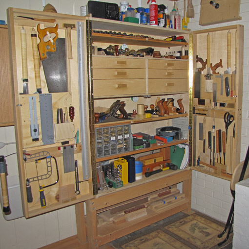
The case is decent quality 3/4″ poplar 7-ply, butt-jointed, glued, and screwed. The rabbeted 1/4″ plywood back and the three-piece drawer bank frame make the case plenty resistant to racking, though it would be better to rabbet the case corners.

The doors are 1×3 poplar assembled with simple glued and screwed butt joints. Each door is nonetheless very sturdy because the 1/4″ plywood panel is glued in grooves all around, and there are several frame structures on the interior. The doors are joined to the case with piano hinges.

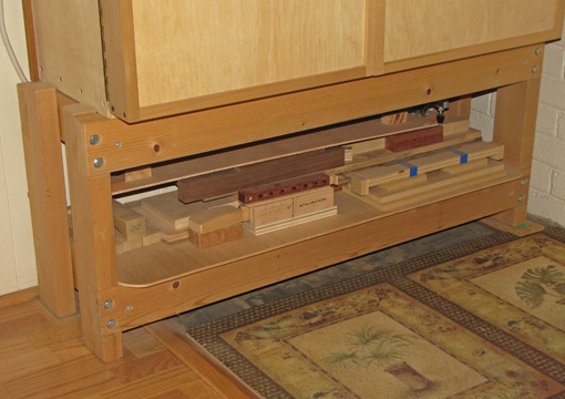
The stand is constructed of notched and screwed 2x4s and contains a shelf for storing jigs and templates. The cabinet is actually standing on the bottom edges of its sides which extend ½” below the bottom. The stiles of the stand extend 1/4″ above the rails to help position the cabinet.
Next: we’ll look at space management, starting with the outside surfaces of the cabinet, and then the overall organization inside.
Author:
• Wednesday, March 23rd, 2011

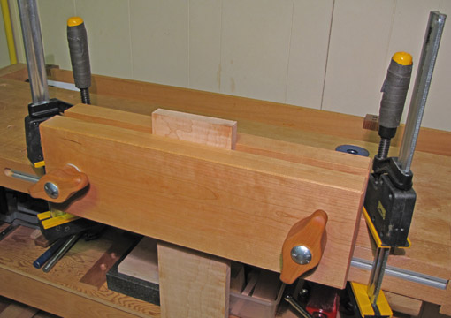
For sawing dovetails, as well as various other tasks, this vise raises the work piece to a more comfortable height than does the typical bench front vise. It was first described by Joseph Moxon, the seventeenth century author of The Art of Joinery. Credit for its revival and refinement goes to Chris Schwarz, editor of Popular Woodworking, who published a modern adaptation of Moxon’s text along with extensive new analysis. Chris published plans for a vise in the December 2010 PW. Stephen Shepherd’s insights and the variations produced by web authors such as Derek Cohen have added to our shared knowledge. What a wonderful example of the vibrancy of current woodworking!

That said, I’ll toss in my two cents: I built my version of the vise and would like to share it with readers.

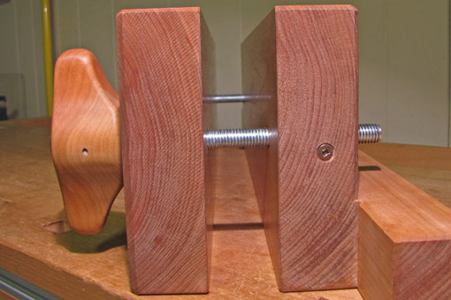
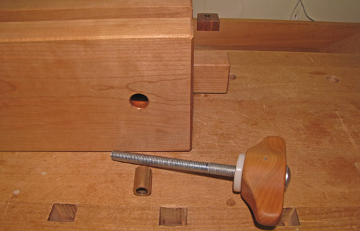
I used an 8/4 cherry board that had been hanging around the shop far too long and $22 of hardware available locally. The vise jaws are 1 3/4″ thick, 6″ high, and 19 1/4″ wide, with a clamping capacity of 14 1/8″ between the bolts. The ½” diameter 8″ carriage bolts are set in functionally shaped handles. Each is secured with a cross pin (finishing nail) passing through a hole drilled in the shaft of the bolt. The handle shape facilitates a one finger spin of the lightly waxed bolt as well as a solid grip to sock the jaws tight. Clamping thickness capacity is at least 2 ½”.

In the front jaw, for smooth operation and to protect the wood, each bolt is supported in a ½” ID, 3/4″ OD, 1 1/8″ long oiled bronze bushing which sits in a stepped hole. To prevent erosion of the bushing, the first 1 1/2″ of the bolt threads is filled with epoxy and the sharp edges of the threads were eased with a file. A 1/4″ thick, ½” ID, 1 5/8″ OD nylon washer, sanded flat, placed between the handle and the front jaw, protects the wood.

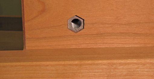
To receive the bolt in the rear jaw, a 2″ long coupling nut was hacksawed to about 1 3/16″ and set from the back side into a stepped hole chiseled to a matching hexagon. This gives more support than a regular hex nut. A wood screw that meets it from the side prevents any chance of the nut twisting in its housing.

The rear cleat, about 1 3/4″ square in section, extends to each side 2 1/4″ beyond the jaws and allows for convenient clamping to the bench. Thanks to Derek Cohen for this idea. I chamfered the edges and finished the wood with one coat of oil-varnish.

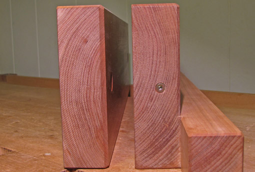
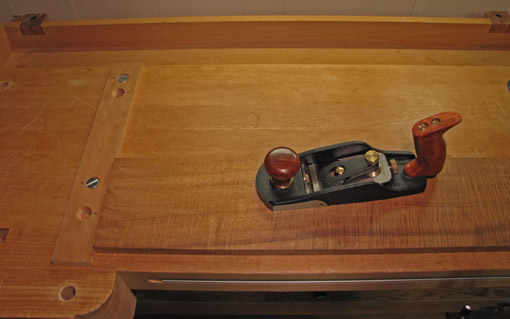
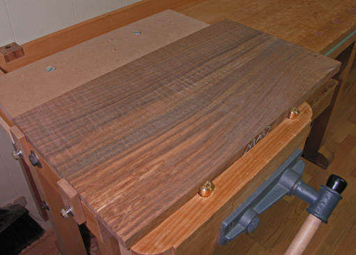
One more detail. Quartersawn wood would have been ideal but I used flatsawn wood because that is all I had available in this thickness. It will inevitably cup and reverse through the seasons. I wanted to avoid a vise that in some seasons would grip the wood only at the central part of the jaw faces and thus make the work piece prone to slipping. I arranged the growth rings as shown in the first photo below and not like the photo beneath it.

Here’s why. I built the vise during the approximate midrange of the yearly humidity cycle in my shop. I left the inner surface of each jaw very slightly concave across its width. As the driest months come along, the inner surface of the front jaw will become more concave while the mating surface of the rear jaw will become flat, then slightly convex. Thus, the grip will be maintained at the limits of the width of the jaws. As the humid months come along, the rear jaw’s inner surface will become more concave (than now) while that of the front jaw will become flat, then slightly convex, again maintaining a good grip of the work piece. Too punctilious you say? Well, the pieces were going to be given some arrangement and I preferred giving it some thought rather than just guessing, and this is one simple solution.


The vise now has had test runs in the shop and I like it a lot. It feels more ergonomic for use with a Western dovetail saw than with a Japanese saw due to differences in the handle angles, but it is good for both.

Author:
• Sunday, January 30th, 2011

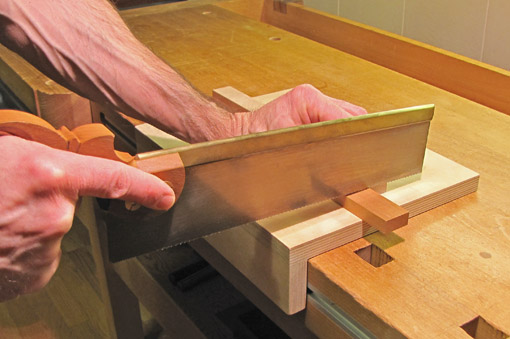
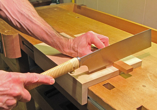
A bench hook is a handy workbench accessory, mostly for crosscutting small parts. This version works well with both Western push saws and Japanese pull saws.

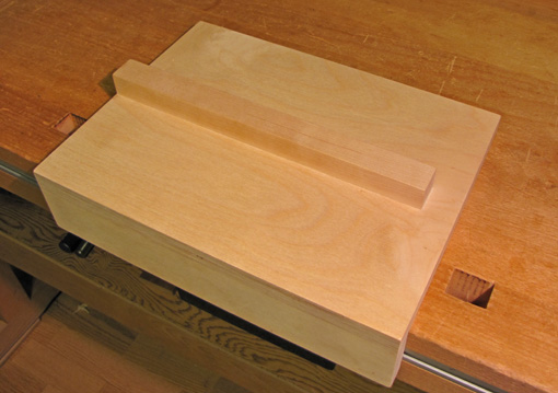
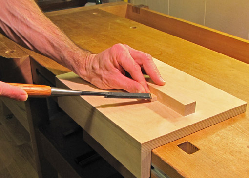
I try to keep workshop jigs and fixtures as simple as possible (“but no simpler,” per Einstein) and this one is no exception. It is constructed from plywood and maple, using simple glue and biscuit joints. The base is 12″ wide by 9″ deep with a 13/16″ high by 1″ wide maple fence at the middle and a 2″ wide cleat for hooking the bench. It could just as well be screwed together. The fence is shortened on the right side for a right-handed woodworker.

For use with push-stroke saws, the jig is simply placed on the bench top with the cleat catching the front edge of the bench. The work is held in place by hand with forward pressure against the front side of the fence. Aided by the sawing pressure, this also holds the bench hook itself in place.

For use with pull-stroke saws, the work is placed against the back side of the fence. Since the sawing pressure is toward the user, it will pull the work against the fence but will also tend to displace the bench hook. This is not a problem for light work because I can lean forward the heel of my left hand against the fence to stabilize the bench hook while gripping the work piece against the far side of the fence with the rest of my hand. For more substantial pieces it is better to secure the bench hook in the front vise of the workbench.

I do not generally use the end of the fence as a guide for the saw, and do not use a fence with 90̊ or 45̊ kerfs, though some may prefer these options. I work to a line marked on the wood and just eyeball noncritical cuts.

This bench hook is unscarred because it is new, replacing one of the same design that got too beat up. As with so many tools in woodworking, it takes a long time and many situations to get a real sense of the effectiveness and versatility of shop jigs. This design has served well over many years so I continued it for the new one, only making it slightly larger.

The bench hook comes in handy for more than sawing. All sorts of work on very small pieces, such as paring and chopping seems to get done on the front side, against the fence. I do not shoot on it; I use a shooting board for that.

Once again, simple and proven effective.

Author:
• Sunday, March 14th, 2010

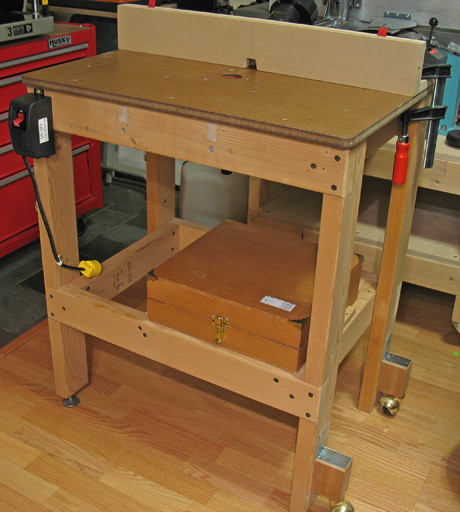
In previous posts, I described my router table and fence. They use a simple approach without router lifts, drop-in fitted plates, table slots, miter gauges, or proprietary tables and fences.

Yet upon noticing a handy-looking router table fence micro adjuster in a catalog, I was tempted. It looked straightforward enough. I studied the item in the store and figured, 24 tpi on the lead screw, well, let’s see, that’s 1/24″ per turn, 1/64″ = 3/8 turn, .004″ = about 1/10 turn. No gradation markings. . . forget it. It would not be easy to move the fence a discrete tiny numerical increment, and why else would I want a micro adjuster?

So how do I accurately adjust my router table fence? The answer is: as directly as possible, preferring consistency over absolute measurements, and using one-sided tolerance woodworking techniques which are easily compensated. For example, if I want grooves for a drawer bottom to be 3/8″ from the edge, I set the fence to a reasonably close 3/8″ and plan the work to cut all the parts with that setting. As an example of one-sided tolerance, to cut a rabbet, use the part that will fit in the rabbet to adjust the fence, adding just a hair of depth. The slight excess of lip is easily trimmed after assembly, whereas too little depth would require lots of corrective planing.

There are rare circumstances, however, when it is helpful to move the fence a tiny, specific numerical distance. If I make a cut with the router table and, for some reason, I do not want to alter the mating part to fit, I use .001″ resolution calipers to measure the difference between the cut part and the mating part and thus the amount I need to move the fence to accurately finish the cut.

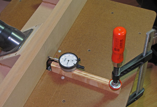
I use one screw to attach an inexpensive dial indicator to a stick which gets clamped on the table with the tip of the indicator against the fence. The fence is then moved according to the direct readout on the indicator. It would be possible permanently rig a dial indicator to the fence and table but that would be too fussy for rare use.

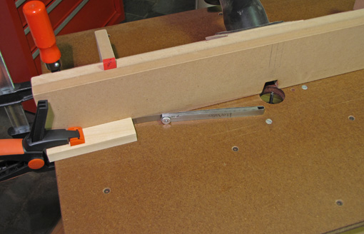
Alternatively, without a dial indicator, to retract the fence, clamp a block to the table near the end of the fence to register the initial fence position, loosen that end of the fence, interpose a feeler gauge, snug the fence up to it, and retighten the fence. To advance the fence, set the feeler gauge against the fence, snug up and clamp the block against it, loosen the fence, remove the feeler gauge, bring the fence against the block, and retighten the fence. The increment at the bit is half the measured amount at the end of the fence. These procedures are far easier and more intuitive to do than to read or write them!

For bit height, I also like to work directly, but if a measured movement is needed, the very fine adjuster with marked gradations on the Bosch 1617 router works well.

In summary, I adjust the router table fence with direct, low-tech methods the vast majority of the time, and very occasionally employ simple methods using basic multipurpose tools (that I already own) to produce specific measured adjustments.

And I saved myself from another mind-cluttering, special-purpose gadget.

Author:
• Friday, December 11th, 2009

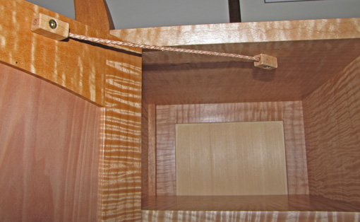
In designing cabinets and boxes, it is often necessary to limit the travel of a door or lid. Hardware options include folding stays, sliding stays, chains, and various types of supports. While some are purely practical and some more elegant, I did not feel any of the manufactured choices I was considering for this pair of small doors was in keeping with the overall nature of the piece. The problem was the metal itself – hard, noisy, overbuilt, and, well, metallic.

I wanted this component to be quiet and organic, so I did some experimenting and came up with a wood and leather concoction that functions well and complements the overall piece. It is also simple.

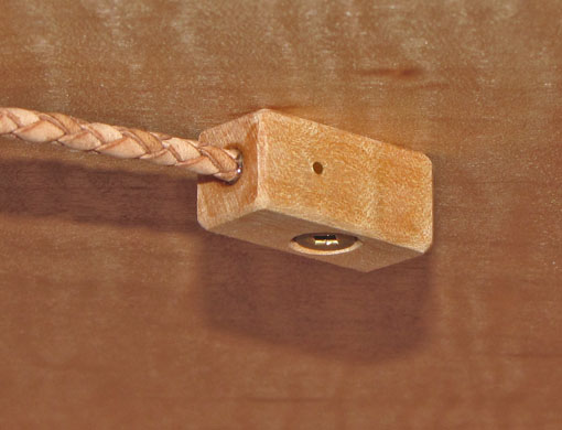
Braided bolo leather cord, 1/8″ diameter, in a tan color that matches the wood, is epoxied into a 1/8″ diameter hole going fully through the length of a 1″ x 7/16″ x 7/16″ maple block. To further secure the cord, a brass 0.050″ wire brad (local Ace Hardware) is gently tapped through a slightly undersized hole crossing the width of the near portion of the block and passing through the cord. The pin is clipped and filed flush at each end. A small countersunk screw attaches the block to the door or cabinet interior.

Experimentation will show where to place the blocks, considering these factors:

  • the desired limit of the door opening
  • a balance between putting the blocks too far away from the hinge side where the cord will be too obtrusive, and too close to the hinge side where too much leverage placed on the cord risks breaking it
  • the blocks must not bump into each other when the door is closed
  • there must be room for the cord to easily tuck away without curling too much when the door is closed (also, avoid twisting the cord)
  • what looks right

The diameter of the cord, up to ½”, and the sizes of the blocks and fasteners would be adjusted according to the overall size of the piece. I sized the components as seemed right for these doors which are about 16″ x 10″. In testing, I was able to break the 1/8″ cord with a strong pull but it certainly is adequate for its task in this project.

I think the bit of desperation involved in the genesis of these stays ultimately helped produce a unique touch to the piece.

Author:
• Sunday, December 06th, 2009

Illustrated here are several uses of the system of holes, Pups, Anchors, and stops described in the previous post. The simplicity of the layout engenders versatility. If it was tailored too narrowly to specific tasks, much of the creative range of the system would be sacrificed. As it is, introducing a piece of scrap wood here and there can effect solutions to the continually evolving work-holding demands of new woodworking projects.

On the left side of the bench, a nice piece of scrap wood acts as a planing stop. It is secured to the bench with countersunk 1/2-13 flat head blots that go into the removable Anchors positioned in holes in the bench top. I prefer the recessed bolts because I am uneasy with protruding metal in the vicinity of a moving hand plane.

Note that the “nice scrap” has an extra pair of holes that allow it to be used in a pair of holes parallel to the length of the bench with Anchors in them. The two pairs of holes in the nice scrap serve as permanent templates for producing other Anchor accessory pieces as needed. This kind of stop is also useful for work with the Domino joiner.

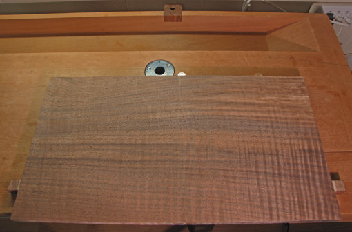
The photo below shows a board blocked on three sides using the stops on the left side of the bench, Pups in the vise chop, and a piece of scrap bolted into Anchors. Note that the pair of holes in the scrap are offset to one side, giving two effective projection widths from the Anchor points. Think of these scraps as extended dogs.

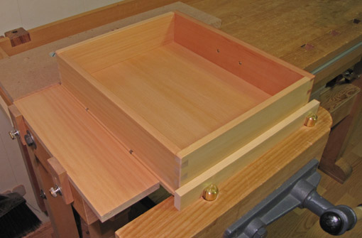
The photo below shows a drawer held in position with creative use of Pups, Anchors, and scrap wood. In this arrangement the top edges of the front and two sides can be planed without the work budging.

On the right side of the bench in the photo below, the regular bench dog and tail vise system is used in conjunction with two Pups in their holes (prairie dogs?) that prevent lateral shifting of the work. This is an alternative to the setup on the left side of the bench and it can also accommodate options with Anchors. This three-sided blocking of the work piece is handy, for example, when scrub planing diagonally across the board, which might be necessary for this piece since it is too wide for my  machine jointer. These systems are also especially handy for planing door frames which inevitably involves frequent changes in direction of attack with the plane.

The main point is that there are surely undiscovered variations and creative adaptations of this system that will evolve as the work demands. With a minimum of hardware and alteration to the workbench, its foundation is simple and easy the way I like it.

Author:
• Wednesday, December 02nd, 2009

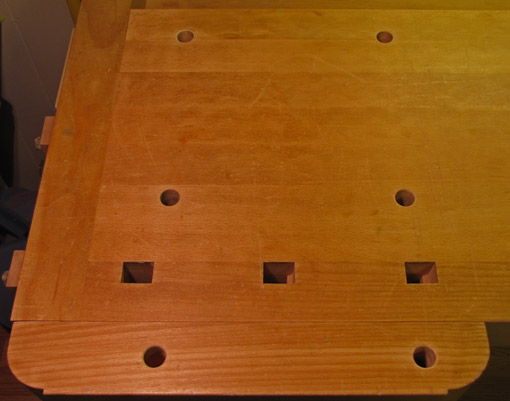
Holding short, wide boards or intermediate assemblies such as drawers and cabinet doors can be awkward on traditional-style workbenches. Attempting to solve these problems, I have been gradually altering my bench to incorporate two helpful products made by Veritas: Bench Pups and Bench Anchors. This involves drilling 3/4″ holes in the bench top with considerable forethought. As with any redesign of a basic tool, true success can be declared only after a long time of use encountering a wide variety of jobs. So, I have tried to research and anticipate well and, so far, so good.

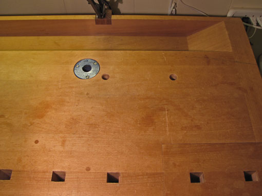
A Bench Pup is a 2 3/8″ long, round, brass bench dog that fits in a 3/4″ hole. A Bench Anchor is essentially a portable 1/2-13 threaded insert that is secured in a 3/4″ hole by means of an expansion system. While the function of the Pup is simple and obvious, the Anchors allow an unlimited variety of stops, boards, and accessories to be secured to bench surfaces. I also added two shop-made dogs on the side of my bench.

Let’s start at the left side of the bench. I wanted a planing stop but not the typical wide slide-up stop at the left end of the bench. The problem for me with that design is that the front vise gets in the way of my left hip when planing. Furthermore, the vise handle is at just the right height to bump into parts that I’d rather not have bumped. This causes me to crane over the work piece, creating lower back stress. So, the first two holes were placed in the bench top near the right end of the front vise. There the Anchors can be placed and a ½” board with countersunk holes can be secured into them with flat head bolts.

The next step is to permit those two holes to do double duty working with the front vise. Two more holes are placed in the bench top, each equidistant from the vise face with one of the first two holes. Then two more holes are placed in the vise chop, equidistant from the face and each in line with one of the pairs in the bench top.

I wanted the holes in the bench top to go fully through to allow access to the Pups and especially the Anchors from underneath. Now, it would have been nifty to arrange the four holes in the top at the corners of a perfect square which would allow one hole spacing to be used in auxiliary boards, but the constraints of my bench and vise hardware did not allow this.

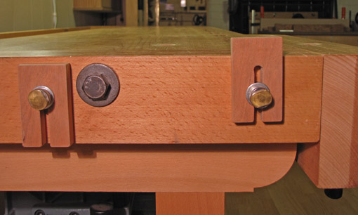
Two shop-made slide-up dogs were added to the left end of the bench. These are secured with 1/4-20 finger bolts that enter threaded inserts planted in the side of the bench.

Now to the right side of the bench. Two holes were placed parallel to the row of square bench dog holes, one slightly to the right of the closing point of the tail vise, and the other about 7″ to the left of the first.

With these alterations to the workbench, I tried to make each hole contribute as much versatility as possible. The next post will show a few of the possibilities for holding work with this system.

The reason I titled this “More workbench upgrades” is to reference an article that I wrote for Popular Woodworking magazine, November 2007 (#165), pages 57-61, “Upgrade Your Workbench,” which readers may find helpful for more ideas on the most important tool in the shop. Back issues are available on the PW site and a short video relating to the article is also on the site.

The little hole drilled into the face of the Bench Pup allows one to lever it up with a small screwdriver or hex key. Thanks to Alejandro Balbis! – who contributed this tip to the December 2009 Popular Woodworking.

Author:
• Saturday, October 31st, 2009

What if there was a way to adjust your work setups in controlled increments of a few thousandths of a inch? And what if this technology would cost next to nothing? Consider the underappreciated shim.

There has been a proliferation of adjusting gadgetry in the woodworking market over the past decade or so. Rip fences, miter gauges, router lifts, thickness planers, and so forth, can be souped up with micrometer adjusters and digital readouts that seem to promise precision in the end product. These devices might add convenience and accuracy to woodworking but only if they are used thoughtfully. The craftsman must be cognizant of the different levels of accuracy required for various tasks and, just as important, of the consequences of inaccuracy on each side of a target. If used mindlessly, these gadgets can easily make a woodworker lose sight of the logic of the construction process.

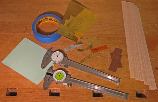
I usually prefer simpler, more intuitive methods that often involve using shims. For example, if a groove cut on the router table needs to be bit wider, a strip of tape applied to the edge of the workpiece or the fence will widen the groove on a second pass by .004″. When I made the fence for the router table, despite doing “everything right,” it required a piece of .002″ plastic shim at each end to make it straight against the Starrett, and some blue tape on the bottom to make it square to the table. It’s just as good as if it came out perfect on the first try.

This is not cheating! This is “microadjusting”.

Shims can also be used to “measure” intentional gaps, such as in fitting a door or drawer. Wood shims are non-marring and can be made to whatever thicknesses you want, which allows you to make and confirm these small measurements according to your artful eye’s desire.

So maybe you made the hinge mortise a bit too deep; you know what to do. Sure, we try to be accurate but we work in the real world and it helps to have a Plan B.

I keep on hand in the shop all sorts of shims, including brass sheets, a book of plastic shim stock, a leaf gauge set, blue tape, paper, and, of course, slices of wood. When, by chance, some good candidates for shims come off the table saw or bandsaw, I toss them in my box o’ blocks. Sometimes I take out dial calipers and measure and mark them.

Remember: it’s OK, it’s microadjusting.