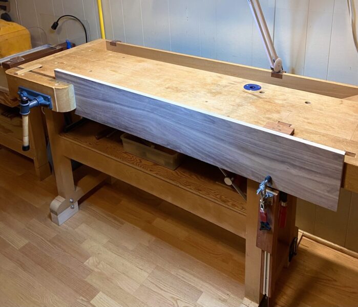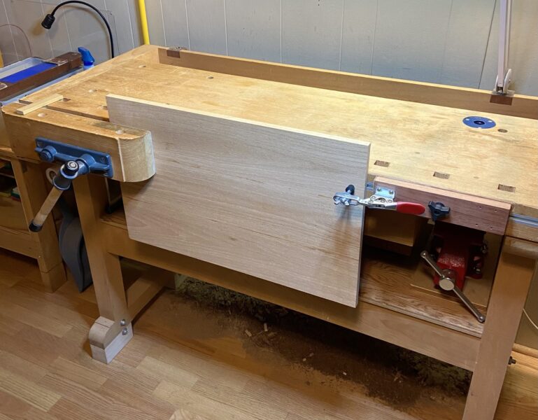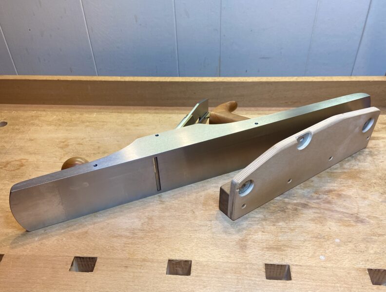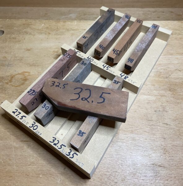
I think it would be good to review and make sense of this handy device that was pictured and cited in the previous post.
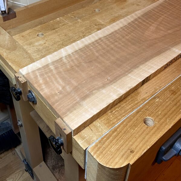
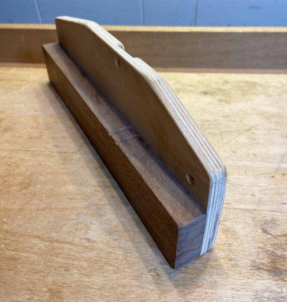
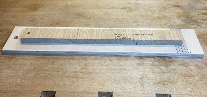
As you can see from the photo above, this is simply a glue-up of three pieces of flat sawn red oak on a base of plywood. It is 11/16” thick, and about 15” from the screwed-down end point on the left to the opposite end where it is measured. I cross sawed it from a much larger piece. The “long” grain (which is essentially stable) is just 1 1/2”.
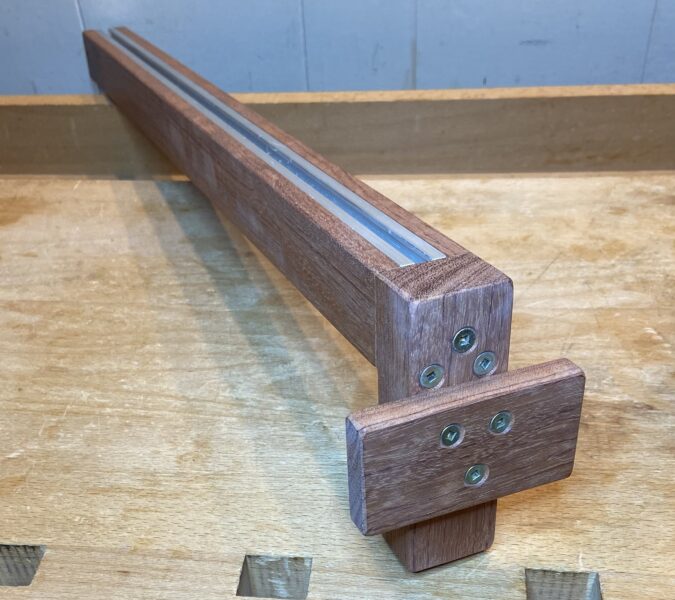
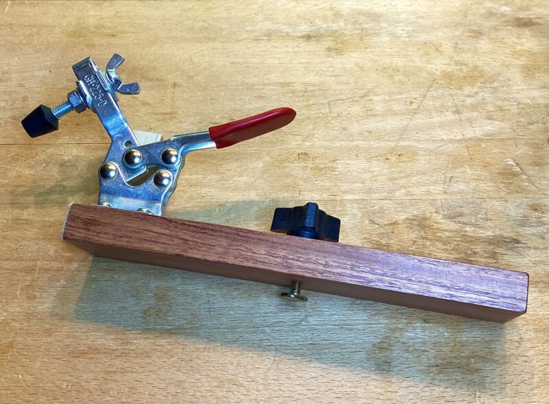
Observe that the glue up is done with pieces in alternating grain orientation to avoid a large curl-shaped change with moisture change. The large amount of exposed end grain allows moisture content and resultant wood movement to change rather quickly with humidity change. Changes of temperature have no significant effect on the wood length.
Note also that this wood has not been finished. Therefore, reduction in expansion and contraction, depending on the type of finish used in a project, does not affect this device.
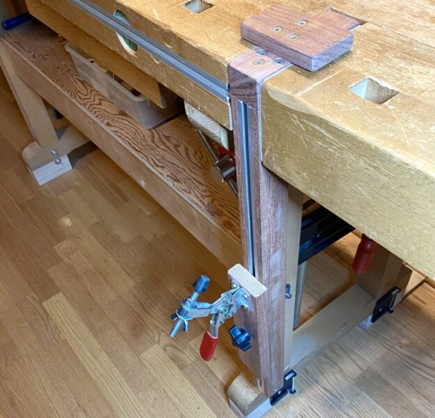
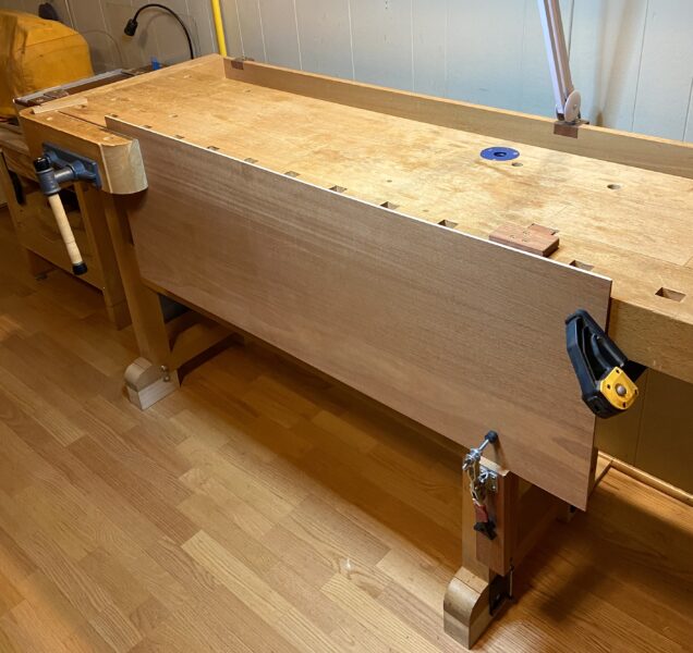
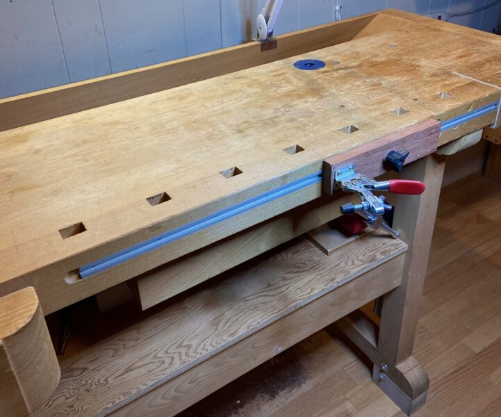
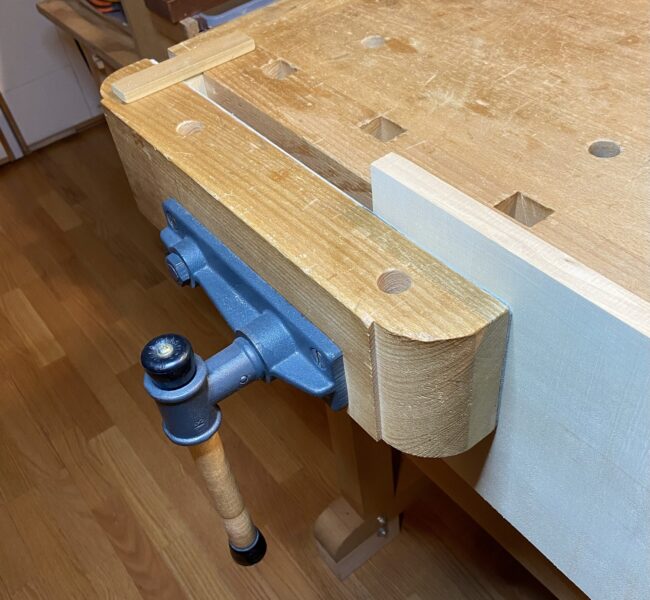
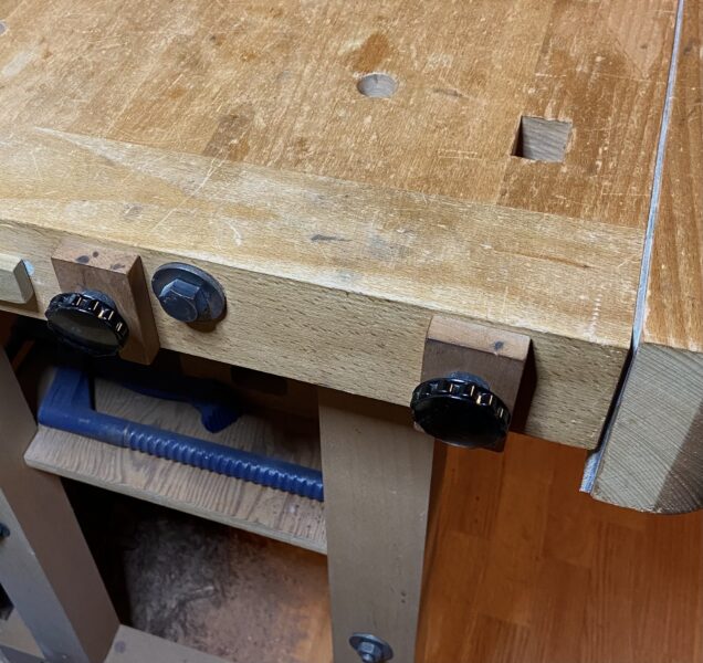
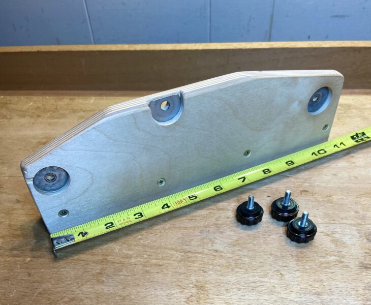
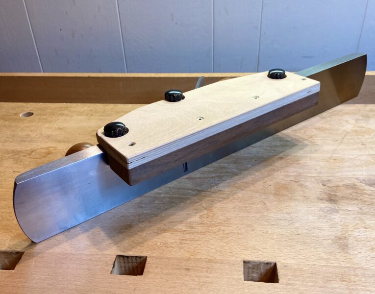
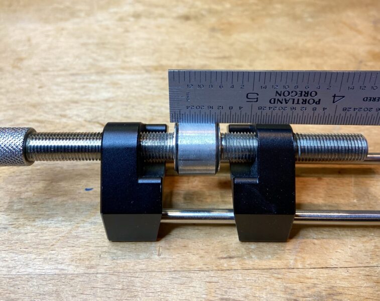
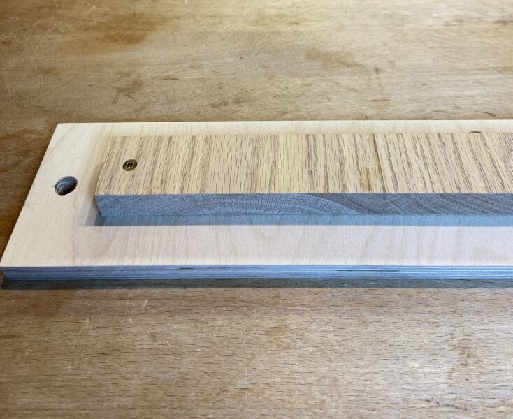
There is a grid of 1/16” gradation on the plywood base at the right end of the red oak. (The grid is actually wider than needed.) A brad in only the plywood meets the bottom side of the oak to prevent it from rolling from the screw hold and dropping down when you pick up the device to look closer. It is stored vertically on the wall using the hole just above screwed end.
left side:
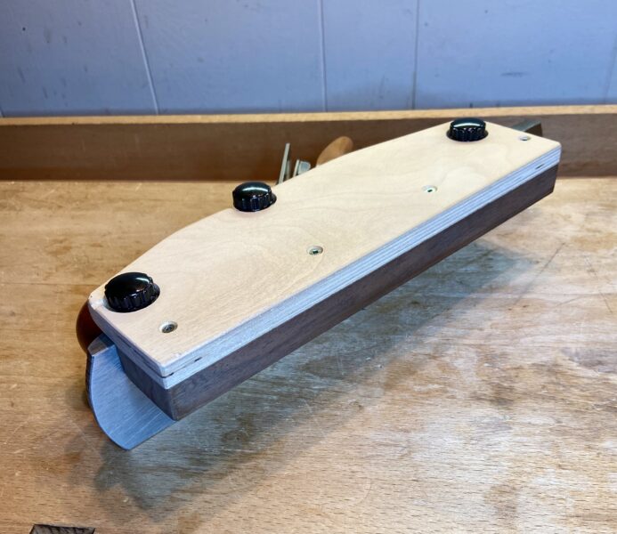
right side:
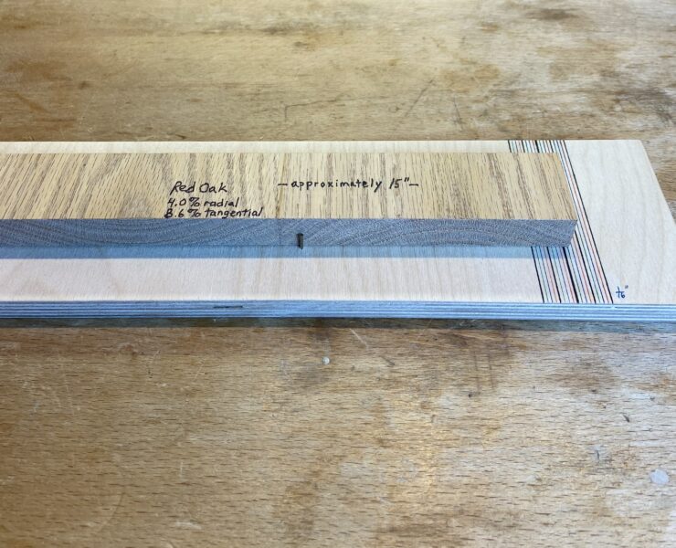
The full range of movement, going from the initial full ~30% water content of wood to fully dried in an oven to 0% content, for red oak, is 4.0% radially and 8.6% tangentially. The approximately “flatsawn” wood in this piece would move somewhere between those two numbers, closer to the 8.6%. Let’s say about 7%.
So, if this piece of red oak went from the ~30% wet to oven dry, it would loose about 7% of its length. 15” would become about 14”. Of course, this never happens in the shop.
What if it really went from a humid shop holding it with 13% moisture content to the shop being drier and holding it with 7% moisture content? The 15” board would shrink to about 14 3/4”. You would see that on the gradation at the right end of the gauge.
Does this really happen? Yes, or at least somewhat that. Also, note that wood shrinkage and expansion actually decreases in range over the years. So, you may observe less than you calculate. However, the expansion-contraction issue is real and must be considered in your construction design.
This simple monitor helps keep you aware of this in a rather large but simple example. I highly recommend it for your shop. It is very easy to make!