You can go a little crazy trying to sort out “oil” finishes, mostly because there is rampant misleading and uninformative labeling among manufacturers who often try to create a mystique surrounding their products.
There are a few key points to help keep things straight:
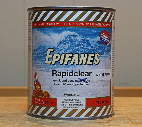
1. Varnish, including wiping varnish such as Waterlox Original, should not be termed an “oil” finish, even though oil (along with a resin) is used in its manufacture. Varnish is a film finish; it cures hard and builds into film thicknesses on the wood.
2. Actual oil finishes, such as linseed oil and tung oil, do not cure hard and do not build appreciably as a film thickness. The exception is polymerized oil.
3. Oil-varnish mixes are just that. The presence of free oil prevents substantial build into a film thickness. These products are notoriously mislabeled as “oil,” such as Watco Danish Oil.
Again, I refer you to Bob Flexner’s wonderfully clear instructive writings, especially his book Understanding Wood Finishing.
Here I am discussing oil-varnish mix. Advantages of this finish include: easy application, nearly mistake-proof, brings out the figure in wood, gives a low key “natural” look, and does not obstruct visual and tactile contact with the wood. One particular place I do not use oil-varnish is inside cabinets or boxes because the smell can accumulate and linger.
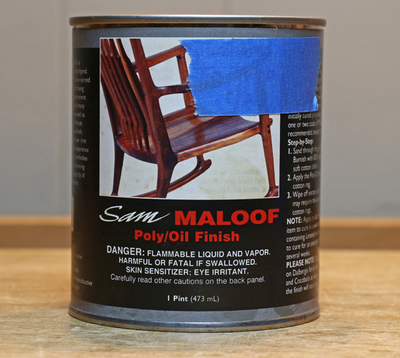
My favorite oil-varnish for more than 30 years has been has been Sam Maloof Poly-Oil from Rockler. What is in it? The label says linseed oil, tung oil, polyurethane, and solvents. In what proportions? Who knows?
What I do know is that it has a nice, thick body in application, it brings out wood figure beautifully without overdoing it, and four coats produce a nice satin sheen after buffing out with a rag. If you want a bit more glow, you can finish up with a paste wax or an oil-wax blend.
The method: For an oil-varnish finish, it pays to sand the wood out to 320 or 400 grit, especially for diffuse porous species like cherry. I slop the stuff on with a rag and wipe off the excess along the grain within a few minutes. Later, I keep checking for “bleed back” of oil from the wood pores of ring-porous species like oak or walnut. I wipe away any little blobs before they start to firm up. This is usually only an issue on the first coat. I keep checking until there are no more blobs because they are a nuisance to sand away if they firm up.
It is difficult to tell by sight or feel when a coat is cured and ready for another coat, so I gauge by smell – once it is nearly gone with a quick sniff test, then it is time for the next coat.
In my experience of trying several oil-varnish finishes, I am not convinced it necessarily makes much difference which oil-varnish mix you use. Watco, for example, is cheaper and I have gotten good results with it. However, I did not like Tried and True because it cured so slowly, at least in its older renditions. I did not find Bush Oil to be anything special. Just my opinions. Still my favorite is Sam’s stuff – maybe because Sam himself was so awesome.
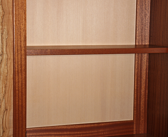
A couple more points regarding “bringing out the grain.” This can sometimes backfire such as on some cherry boards where an oil-varnish mix can produce an unpleasant blotchy look. On the other hand, a single coat of oil-varnish might pleasingly emphasize figure and then you can follow up with a few coats of wiping varnish. Note that the oil-varnish must be cured (the smell is gone). Of course, the great rule of finishing applies – test first.
Next: water-based finish