Tag-Archive for ◊ jointer-planer combo ◊

Author:
• Saturday, April 30th, 2022
Hammer A3-31 infeed adjustment bolts

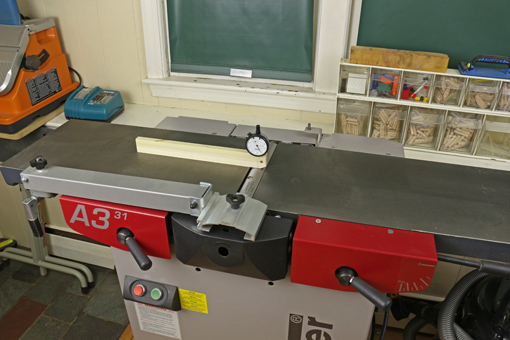
Lots of information can be found on this website about jointer-planer combination machines and the Hammer A3-31 in particular. I have received many inquiries, especially regarding setup and adjustment of the Hammer. One thing that I have not covered in detail is how to make the infeed and outfeed tables parallel to each other along their lengths. This is quite doable but not simple. 

Let us first set the context. As described in detail here, there are several logical steps to adjusting the jointer. In summary:

1. Start by verifying the flatness of the tables.

2. The width of the outfeed table is then made parallel to the cutterblock

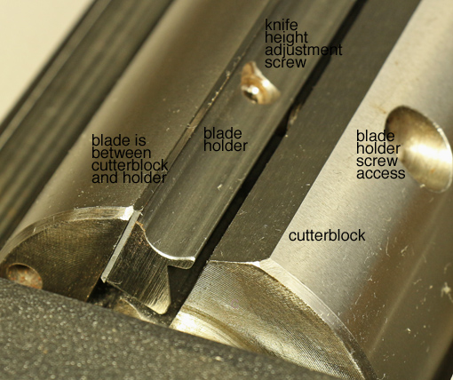
3. The arc of the cutting blades must be consistently adjusted relative to the outfeed table. Here is a practical and accurate method applicable to most machines.

And here are the nuts and bolts on the A3-31.

4. The infeed table and outfeed table are then made parallel across their widths by adjusting the infeed table. Step 4 here describes the details, including for the Hammer. 

5. And now for the tricky part. The infeed and outfeed tables must be made parallel along their lengths.

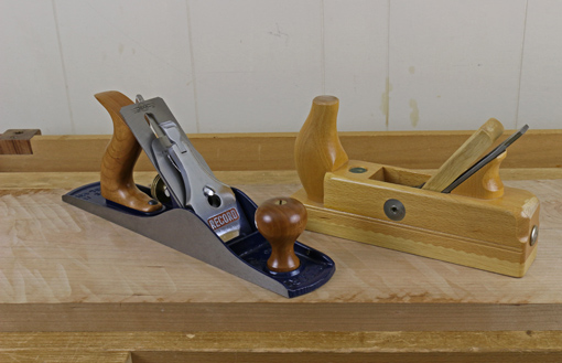
For reasons similar to wanting a hand jointer plane to have a flat sole, so should the machine tables be adjusted. In my opinion, this adjustment should be done with a one-sided tolerance. Aim for the tables to be parallel, but a trace of convexity, like the letter “A,” is OK, but there should be no valley, like the letter “V.”

So, how is this done on the A3-31? In those earlier posts, I referred to “geometry” without presenting the details. You could work hit-or-miss to make the adjustment, but with four points of adjustment involved, it would probably be unnerving and cause you to give up, and then tolerate using a poorly adjusted jointer, which will in turn wreak all sorts of ugly havoc on your ensuing work. So, really, it is worth deciphering my geometric method. It works. 

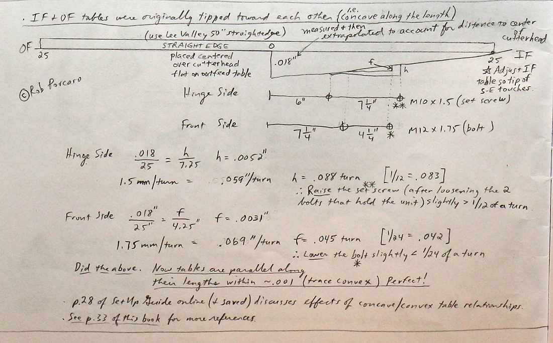
I attached my handwritten notes, made years ago. Click on the little picture below for a full-size version. 

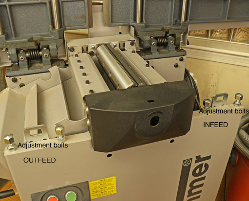
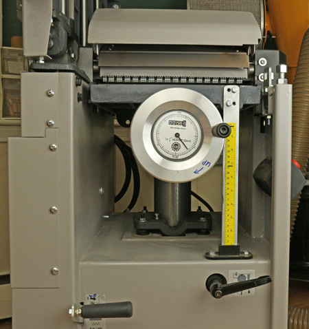
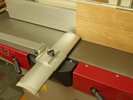
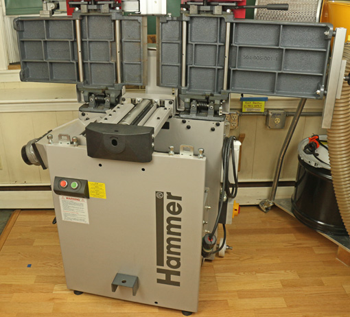
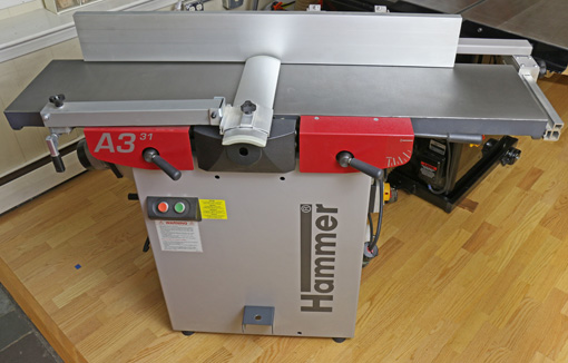
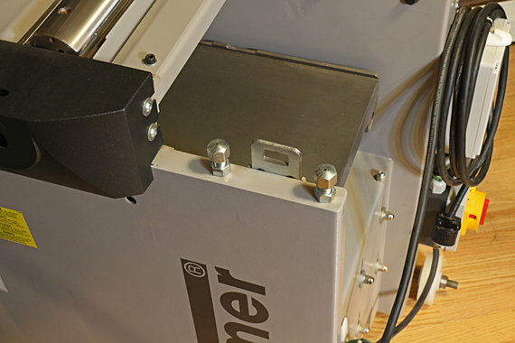
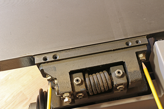
The front-side adjustment bolts are shown in the photo at the top of this post. 

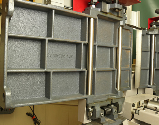
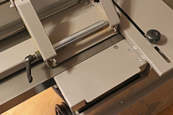
The hinge-side adjustment screws are found under this plate:

Hammer A3-31 back plate

The pencils are pointing to them: 

Hammer A3-31 hinge-side set screws

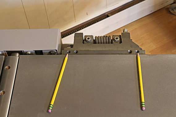
These bolts must be both be loosened to allow the set screws to move: 

Hammer A3-31 hinge-side bolts

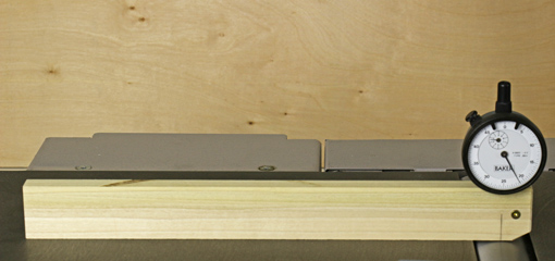
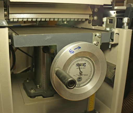
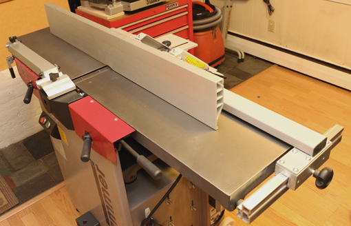
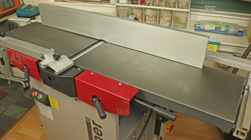
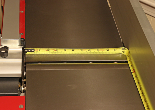
The method starts with placing a straightedge to extend the full length of the infeed table with a sufficient amount to also have a good register on the outfeed table. The infeed table starts low and then is adjusted upward to the first touch on the straight edge. If you have done all the previous work as described above, the place of the touch will tell you how the tables are aligned. In my machine, the tables were delivered tilted toward each other, like a “V,” so the first touch of the straightedge was at the outer end of the infeed table.  

Measure the gap as shown in my notes. Note then that I have simply diagrammed similar triangles among the straightedge-table and the pairs of adjustment screws, and calculated the amount of adjustment to be made at the appropriate screws. I then converted that into how much to turn each screw based on the thread pitch. 

OK, I think you can see why I did not include this in my original set of posts! It is a bit painful. I like math so I admit to a bit of joy in working this out, but for those A3-31 owners not so disposed, contact me and I’ll try to help. 

Thankfully, the machine holds its adjustments very well. 

Author:
• Wednesday, December 31st, 2014

jointer alignment

After the posts on jointer-planer combination machines and the Hammer A3-31, some readers emailed questions about how to align the tables and knives so the jointer does what it is supposed to do – produce flat, straight surfaces on wood.

Here are the steps in tuning jointer tables and knives. The methods of adjustment will, of course, depend on the make and model of your machine, but hopefully this will clarify the overall logic of the process. Methods specific to the A3-31 are entered within brackets.

1. The cutterhead rotates on its axis. This is the reference to which all the other parts must be aligned.

Further, the tables should be flat. Of course, they are not perfect but if they are pretty good – not dished/bumped/twisted more than a few thou – then go with what you have. Some localized imperfections will cancel out with the procedures described here. In any case, practical woodworking, not perfection, is the goal.

2. Check the parallelism of the cutterhead block to the outfeed table. This step is often neglected. Make a wooden holder for a dial indicator as shown in the photo. Alternatively, a feeler gauge and the stock of a square can be used but this is awkward.

jointer alignment

The reading is noted when the tip of the indicator is at the top of the cutterhead circle (i.e. its most retracted reading) at several points across the width. Use the same portion of the circumference of the cutterhead for all of the readings to negate any imperfections in the roundness of the cutterhead.

If the indicator readings are not consistent across the width, the tilt of the outfeed table on its long axis must be adjusted to make it parallel with the cutterhead. My outfeed table is parallel to the cutterhead within half a thou across the full width.

[On the A3-31, the two M12 x 1.75 bolts on the handle side under the outfeed table are adjusted. Calculate the amount of turn required and work from there rather than guessing. You should not have to adjust from the hinge side for this.] Other jointers may require shimming where the table and base castings meet on one side.

3. Adjust the height of the outfeed table relative to the knife arc. The knife arc should be consistent for all three blades and all across the cutterhead. On most jointers, this is adjusted by means of jackscrews in the blade holder. Really you are making the knife arcs consistent with the cutterhead, which previously has been determined to be parallel with the outfeed table. Aim for the top of the knife arc to be a thou or two above the infeed outfeed table using the method described in this post.

Hopefully, you are in the range of requiring only small adjustments of a few of the jackscrews. However, if it is way off for all of the knives, the outfeed table should be adjusted as a unit. [For the A3-31, this latter adjustment is found under the left side red plate. Page 33 of the User Manual shows where it is and how to move it.]

At this point, you should have a cutterblock parallel to the outfeed table, three knife arcs also parallel to the outfeed table, and the top of the arcs should be about .001 – .002” above the outfeed table. Only now should you turn your attention to the infeed table.

Note that wear of the knife edges may later require very slight adjustment in the overall height of the outfeed table. However, the parallelism should be retained.

4. Make the infeed table parallel to the outfeed table across their widths. Assess this just at the cutterhead-end of the infeed table. Use the dial indicator jig or place a 12” straightedge on the outfeed table and extend it past the cutterhead just an inch or two over the infeed table.

Adjust the infeed table using the regular depth-of-cut lever to about the shallowest cut. Observe the dial indicator or use a feeler gauge under the straightedge to check across the width of the infeed table for parallelism of the tables. If the tables are out of parallel, it is easiest to retain the outfeed table settings and adjust the tilt of only the infeed table along its long axis.

[On the A3-31, adjust the two M12x1.75 bolts on the handle side under the infeed table. Again, calculate the amount needed and work from there rather than guessing.] Other jointers may require shimming where the table and base castings meet on one side

5. Finally, adjust the infeed table so the infeed table and the outfeed table are parallel along their lengths. Assess this with the longest, best straightedge that you can find. You do not want the tables tipped in toward each other at all (like a V), in my opinion. You want them parallel or, if anything, a trace tipped away from each other (like an A).

It is easiest to retain the outfeed table settings and make the adjustment only on the infeed table. It is tilted on its short axis only by making equal adjustments on both sides of the table so as not to disturb what was accomplished in step 4. Again, the specifics will vary among machines. The intent here is to explain the overall logic.

[To adjust this on the A3-31 you have to work on both sides of the infeed table. On the near side are the M12x1.75 bolts. On the hinge side there are M10x1.5 set screws, accessed under the plate cover. To make a directed adjustment, rather than by trial and error, there is some geometry required. The Hammer manual does not cover this. I’ve done the geometry and it works but to write and diagram it is beyond the intent of this post. Hey Hammer, how about updating that 2005 manual to reflect the current model machine!]

The object of all of this is to get the machine to produce surfaces within the tolerances you need for the work you want to do. That is the answer to the question of how precise these adjustments need to be. Practical woodworking, not perfection, is the goal.

Author:
• Wednesday, August 20th, 2014

Hammer A3-31

This final installment in the series will discuss changing blades in the Hammer A3-31 and some summary thoughts on jointer-planer combo machines. [The entire series can be viewed here.]

With some jointers and planers, changing blades is a tedious chore. Long ago, I struggled with the old spring-loaded jackscrew system on a jointer. Brutal. By contrast, changing blades on the Tersa cutterhead that was in the Inca jointer-planer was almost unbelievably easy and fast. The OEM system on the Dewalt DW735 planer was quite easy, and now with the Shelix cutterhead with carbide-tipped inserts installed, changing blades is practically a non-issue.

The system for changing and adjusting the blades on the A3-31 is very good, though not quite the slam dunk of a Tersa. Each of the three blades has holes that neatly register on bosses on the blade holder, which is secured in a slot in the cutterhead with four hex socket screws using the provided T-handle wrench. (See the photo above.) This is easy to do, though a cutterhead lock would make it easier.

If necessary, the blade holder-blade assembly can be adjusted for height with the four adjustment screws within the holder block. These can be used to make a consistent projection of the knife in relation to the outfeed bed across its full width. Further, the height of the outfeed table is adjustable to set its overall relationship to the arc of the knife edges.

The factory settings, which I assessed when the machine was new and the knives were fresh, were excellent; no changes needed! So, when I installed replacement knives, everything should stay the same, right? Well, it worked out pretty well, maybe actually well enough, but not quite to my satisfaction. Somehow, despite great care on my part, gremlins sneaked in and I had to fiddle with the height adjustment screws to get an a consistent projection across the width. (This is not a matter of a difference in the overall projection related to worn versus fresh knife edges.) The manual explains a simple assessment procedure to help get it right and I am happy with the results. Note that perfection is not necessary for this. By the way, another option is the helical insert cutterhead available for the A3-31 from Hammer.

Here’s the key: the machine performs accurately, consistently, and efficiently. I get the results I need to make high quality things from wood. This is what matters.

In summary:

1. For the reasons explained in this series, I highly recommend a 12″ jointer-planer combination machine for the small shop woodworker.

2. After 2 1/2 years experience with the Hammer A3-31, I heartily recommend it. As with any machine, there are a few shortcomings (for this fastidious woodworker), which I’ve covered, but this is an excellent machine that can be a great partner as you pursue excellent woodworking. I cannot fairly compare it to corresponding offerings from Minimax, Jet, Rojek, Grizzly, and Rikon because I haven’t used them, and I’d bet the $7,000 Felder AD-531 outshines all of these, but I can say I’m very glad I have the Hammer A3-31.

Author:
• Wednesday, August 13th, 2014

Hammer A3-31

Now for a look at the parts and systems of the Hammer A3-31 that can be adjusted and tuned, with particular consideration to the ease, accuracy, and durability of the adjustments.

Jointer beds

When the machine arrived, the beds were slightly out of parallel to each other across their widths (i.e. in twist) – by .006″ over the 12″ width. Not bad, but having seen the potential in the excellent flatness of the beds, I wanted to improve their alignment.

Since the alignment of the outfeed table to the knife arc was fine from the factory, the twist was easily removed by adjusting only the two bolts (see the photo above) on the operator side of the infeed table to make the tables parallel within .001″.

Next, using a long straightedge, I determined that the infeed and outfeed beds were tipped along their lengths toward each other. The gap at the middle was 0.018″. To my mind, this is like have a concavity along the full length of a jointer plane sole and would make accurate jointing difficult at best.

Again, the correction was made by adjusting only the infeed table. This was a more complicated adjustment involving the pair of bolts on the operator side and a pair of setscrews, accessed under a removable panel, on the hinge side. Each of each pair of screws must be adjusted by a different amount. To make a long story short, I did a little trigonometry to prevent having to do it by trial and error. The result: cha-ching! The beds are parallel along their length within .001″.

Unfortunately, the Setup Guide, which covers these adjustments and is available as a pdf on the Hammer website, is out of date (copyright 2005). It references an earlier design of the machine and much of the adjustment parts have changed. Fortunately, Hammer makes knowledgeable technicians available by phone who were generous with their time in helping me understand the machine.

I called Hammer this week in anticipation of this post, and they favorably received my suggestion to update the Setup Guide. The User Manual, included in print with the machine and also available online, is more current and clearly explains assembly, basic adjustments, operation, maintenance, and so forth.

Planer bed

I tested this on a performance basis by planing an 11 3/8″-wide board, and by planing two narrow sticks simultaneously sent into the planer at the outer width of it. From the factory, the planing parallelism was within one thou. Wow! This is adjustable if ever needed.

Digital handwheel

This accessory, which I have found very helpful, was calibrated using the information in the Setup Guide. Reading it takes a bit of getting used to because the numerals indicate decimal inches while the hash mark increments are actually metric that approximates imperial. It is really not a problem though.

Hammer A3-31

Fence

Setting up the fence accurately went according to directions, though it does take some care. To maintain a consistent angle, it is important when adjusting the side-to-side position of the fence in use to hold the sliding bracket down firmly on the extruded track while tightening the knob.

In summary, the A3-31 can be tuned to a high degree of accuracy. There are some finicky steps for those who want to tune it really well. Some documentation is lacking but help is available.

The most welcome feature is that the adjustments hold solidly over time and when converting back and forth from jointer to planer mode. This is invaluable.

Next: one more installment – knife changing and an overview.

Author:
• Friday, August 08th, 2014

Hammer A#-31

Let’s take a detailed look at the Hammer A3-31.

When considering a new machine or any tool, I first assess the quality of the key parts that cannot be altered by the user but are accessible to direct evaluation. Here’s how the A3-31 stacks up in this regard.

1. Bed flatness is excellent. Against a Starrett straightedge, the jointer infeed table is within .001″ along its length and .002″-.003″ on the diagonals. The outfeed table is just a hair concave along its length, .003″-.004″, and the diagonals are off by only .002″-.005″. The planer table is within .002″ along its length and .003″ on the diagonals.

This all is excellent, well within Hammer’s spec of .006″, and is an important factor in how accurately the machine can be tuned. Furthermore, the beds are heavy and constructed with thick ribbing, as seen above.

2. The planer feed mechanism does not balk with 12″ wide boards. The steel drive rollers control the board unyieldingly, yet the indentations made by the infeed roller are shallow enough to disappear when the final pass is very light. With good technique, snipe is about as minimal as it gets.

The feed speed is 6.5 meters/minute (21.3 feet/minute), which makes the three-knife cutterhead at 6000RPM produce 70 cuts per inch, typical for jointer-planers in this class. Compared to the DeWalt 735 (with a stock cutterhead) at 96 cpi in “dimensioning” mode and a phenomenal 179 cpi at the slower “finishing” feed speed, the A3-31’s 70 cpi may seem a bit rough but in fact it seems to strike a good balance between producing an excellent surface and working at a good pace.

Hammer A3-31

3. I like the Euro-style safety guard better than the spring-loaded “pork chop” style. I always use paddles for face jointing and it is easy to pass the board under the narrow guard, which is height-adjustable using the knob at the far left in the photo below.

Hammer A3-31

For edge jointing the guard can be adjusted laterally to expose the minimum width of cutterhead. It would be better if the guard was hinged so half of it would hang down when it is adjusted very far toward the user side of the machine – but it’s not in that position too often so it hasn’t been a problem. The hinge feature is present on the company’s higher priced models.

Hammer A3-31

4. Dust collection, as I mentioned earlier, is just wonderful, for jointing and planing. This helps a lot in my small shop.

5. The construction of the aluminum fence makes it very stiff. It is flat within .001″ in all directions and I cannot detect any twist. It is adjusted back and forth by using the knob (to the right in the photo below) and sliding the bracket on the extrusion track.

A slight complaint is that the squareness of the fence to the table cannot be made exactly consistent throughout its full adjustment range and most of its length, probably due to minute errors stacking up. However, the discrepancies are quite small, and by finding favorite locations for the fence, I have had no problem getting nice square edges on long boards.

Hammer A3-31

From the back view, you can see that not much sticks out – only the rear cutterblock cover. For most fence positions, the net depth of the unit is about the same with the jointer beds down or raised.

Hammer A3-31

Other key components that I cannot directly assess seem very good based on indirect observations and working with the machine. Machining and part formation looks neat throughout, with no ill-fitting components. The motor has excellent power and does not get overheated. Hand adjusted parts, such as the planer bed adjustment are very smooth, and the machine runs with that nice low hum suggestive of quality.

The same outfit that makes Hammer machines also makes the much more expensive Felder line. A Felder 12″ jointer-planer lists at over $7000 (ouch, my hand just cramped up at the keyboard), which is more than twice the price of the Hammer A3-31. I figure that the expertise and institutional experience applied to the Felder line must bleed over into the Hammer line. I’d bet it’s more than half the machine for half the price.

Next: The final next installment in the series will cover tuning and results.

Category: Tools and Shop  | Tags:  | Comments off
Author:
• Thursday, July 31st, 2014

Hammer A3-31

Having established in the previous post a rationale for this type of machine in a small woodshop, let’s take a look at the Hammer A3-31, which I’ve been using for the past two and a half years.

Getting it into the shop

I’m afraid I must start with one of the few problems I have experienced with the A3-31: getting it into my shop. The mobility kit uses a single axle that attaches to the base parallel to the 55″ jointer bed, along with 4″ wheels that simply turn in one plane – they do not swivel. A lifting bar is inserted into a cleat near the bottom of the base of the machine to roll it in a straight line and make partial J turns.

The top photo shows the lifting bar in place. One wheel is visible at the lower right of the machine base.

The system works well in the shop but it will not get the machine through the 32″ doorways in my house or the 36″ doorway of my shop. To make matters worse, the A3-31 was shipped on a pallet built for a special narrow-fork pallet jack. I ended up having to transfer the machine from the pallet onto a dolly that I built and use plywood sheets to get it over doorway bumps – a big hassle. If you have a garage shop or other wide doorway, all of this is not a problem.

To solve this problem, I wonder if Hammer could include a short axle to attach to the base perpendicular to the jointer bed to be used with a matching cleat. It might work only with the jointer beds raised but that would be good enough to just get the machine through narrow doors. Hey, Hammer: this would help many small shop woodworkers.

Now on to happy issues.

In order of frequency, here are the most common concerns among woodworkers that I’ve heard and read about j-p combo machines:

1. Changing between jointing and planing modes.

Fuhgeddaboudit. To go from jointing to planing, the fence stays in place. You lift the jointer beds as a unit, then flip the dust hood and reattach the hose. The tables remain parallel when raised so the effective width of the machine is approximately unchanged. The planer bed is cranked into position with an extremely smooth and fast mechanism. The jointer beds return to position precisely. Really, it’s all fast and easy.

Here are the beds lifted:

Hammer A#-31

And here the dust hood is in place for planing with the hose attached:

Hammer A3-31

This is the planer infeed with the bed raised into place. The adjustment mechanism has the helpful, optional “digital handwheel.”

Hammer A3-31

2. Jointer bed length

Is a 55″ jointer bed long enough? It sure is for anything I do. I have no problem routinely accurately jointing rough boards 6′ long. In my opinion, there is no need to have the entire board length supported on either the infeed or outfeed table to do accurate jointing.

If you want more length, Hammer offers optional extensions for jointing and planing that look like they attach very easily.

Hammer A3-31

3. Dust collection

Can the dust hood contraption really work in both jointer and planer modes? Yes! The A3-31 is nearly perfect when used with my Oneida Mini Gorilla cyclone collector. It is the tidiest machine I’ve ever used.

4. Accuracy

Can a combination machine be as accurate as single function machines? This was my number one concern when contemplating the purchase.

For a given quality level, having used the Inca for many years, and now the Hammer, I say the answer is yes. I did have to do considerable work tuning the A3-31 to my liking but I’m a rather fastidious worker. (“Really, Rob? You? Get outta here, I wouldn’t have imagined . . .”) The key is that this machine can be tuned and it holds the settings. More on this in a future post.

5. Power and mass

Are these machines, in this size range, just toys for dilettantes? OK, now I’m getting a little annoyed. Just fuhgeddaboudit, OK? The motor is listed at 14 amps/220V and does not balk at planing full width boards. The mass of the beds, the quiet operation, and the results it produces are real deal.

[This extended review of the A3-31 and the general topic of j-p combo machines are unsolicited and uncompensated.]

Next: getting inside the machine.

Author:
• Sunday, July 13th, 2014

hand jointing

In the previous post in this series, I recounted my stock preparation history culminating with the Hammer A3-31. Prior to discussing the ins and outs of the Hammer machine, let’s look at the rationale for a combination jointer-planer in the small shop.

I’m guessing most of us share the following woodworking profile. We have:

  • A strong desire to build things from wood that exceeds the desire to dawdle with woodworking tools.
  • Less time than we want for making things.
  • Less shop space than we’d like.
  • Less money than we want.

To get a pile of wood transformed into a finished project, the stuff needs to be taken to the desired thicknesses, with flat parallel surfaces and a straight, square edge before being ripped to width and crosscut.

Here are some options:

1. Handwork/hybrid

Doing it all by hand is just too slow and tedious for most of us, but a hybrid approach employing a portable thickness planer is very practical. One face is made flat but very rough using scrub and jack planes, just enough so it does not rock or distort on the planer bed, and there is no bow (lengthwise curve on the face). The planer flattens the opposite face, the board is then flipped and the planer makes the first face flat and parallel. Then hand plane a straight edge.

Don’t forget too that a well-tuned bandsaw with adequate blade height can do a pretty good job as a jointer and thicknesser followed by clean up with hand planes.

2. Exceptions

It does pay to be able to fully prepare a board entirely by hand just as a baseball player must be able to bunt – it isn’t used often but a complete player artfully brings up the skill when needed.

Some boards are too short to safely feed to a thickness planer and hand work is a must.

Also, there is an occasional board in which I want to preserve every hair’s breadth of thickness, and conservatively flattening one face by hand is a less risky method.

For very wide slabs, elaborate router jigs can be set up but finding a local commercial shop with a megabeast thickness sander makes more sense to me.

3. Separate jointer and planer machines

The big problem here is that jointers with widths that approach even inexpensive portable thickness planers are big and expensive. To me, it makes little sense in terms of expense, space, and work efficiency for most small shop furniture makers to have a $2000, 600-pound, 8″ jointer with a 7 foot bed paired with a 13″ thickness planer. Or how about 5 or 6 thou for a 900 pound 12″ jointer?

One interesting exception to this mismatch situation is Grizzly’s G0706 12″ jointer that has a 60″ bed.

4. Combination jointer-planer

In a single machine with a fairly small footprint, you get an excellent 12″ of planing and matching jointing capacity. This opens up a world of managing wide boards with ease. This is value.

There is a range of prices starting at about $1800 up to twice that, among options that include Rikon, Grizzly, Jet, Rojek, Minimax and Hammer. Pair one of these bad boys with a steel frame bandsaw with a matching 12″ capacity and life is very good.

Lower budget 10″ models are available, including Rikon, Jet, and Grizzly. I will say that I really appreciate the extra two inches and extra beefiness of my current Hammer over the 10″ Inca I had. Hey, how about 16″? Sure, if you’ve got the space and money, but for most of us it’s not necessary for most furniture making.

In the next post in this series, I’ll go into some detail about my Hammer A3-31. Previewing, here are two non-issues: bed length and change over between functions.

Hammer A#-31

Author:
• Monday, June 23rd, 2014

bed width

Stock preparation is the essential foundation for any woodworking project, and there are three keys to doing it well: accuracy, efficiency, and knowledge. A jointer-planer combo machine can be a big help.

There are countless pitfalls in stock preparation that can haunt even the most skillful woodworking that may follow. Twist, convex edges, and bowed surfaces are common inaccuracies that create problems. As for efficiency, well, I like making things and I do not want to spend forever grunting out stock, so the noise emanating from well-tuned machinery is music to my ears at the start of a project. Still, none of this works if a woodworker fails to appreciate wood movement from moisture exchange as well as from stresses created in the drying process.

By way of explaining how I settled on the combination machine, let me recount my stock preparation history. I think many readers will relate to much of it. Very early on, two things became obvious. First, it is very limiting to use only the thicknesses available in pre-dimensioned hardwoods, and second, dimensioning with only hand tools is slow and really not a lot of fun.

So, I got one of those ubiquitous cast iron 6″ jointers, and rigged up a marginally effective way to also use it as a thicknesser. Then, some years later, in the late 1980s, I bought a Ryobi AP-10 portable thickness planer, and its 10″ capacity made me feel like I was in heaven (“. . . man”). Still, I was stuck with only 6″ of machine jointing capacity and, despite trying the workarounds found in the tips sections of magazines, I was still doing too much hand work and longed for more machine jointing width, especially since I enjoy using fairly wide boards in my projects.

Enter, the Inca 10″ over-under jointer-planer. This wonderfully accurate machine, with its precise cast aluminum tables and great Tersa cutterhead, served well in my shop for more than ten years, perched on the feature-rich, battleship-grade stand I made for it. The only thing the dear Inca lacked was a lot of muscle, and so when I upgraded, I felt at peace selling it to a musical instrument maker.

Inca jointer-planer

Inca jointer-planer

Now, after 2 1/2 years of using the Hammer A3-31, and privately answering many inquiries about it, I’m ready to write. The opening photo shows off its width. I will discuss the A3-31 in some detail (spoiler alert) – I like it! – but will precede that with a post to consider the merits of the whole idea of a jointer-planer combo.

One more thing. I made the case several years ago for a portable jointer-planer as an excellent choice for a first machine for small-shop woodworkers making furniture and accessories. After many discussions with woodworkers during the ensuing years, I still hold that opinion, though I certainly understand how many feel a bandsaw should be first in line (I place it second) among other valid opinions.

Keep in mind that with a thickness planer as the only machine available, the initial jointing of one face by hand (which, again, I’d rather not do!) only has to produce a surface that will sit on the planer bed without twist, bow, or flex. It can be ugly with tearout, scrub plane gutters, or whatever; it just has to register on the bed so the planer can produce a flat surface on the opposite face. Then the board is flipped over, etc.