For a long time, I have not liked the leather honing wheel on the Tormek. I never used it for general sharpening because I prefer stones, but even for knives, gouges, and an occasional touch up of other edges, I find it fragments easily and does not hold the honing compound as well as I would like.
I finally got around to setting up the wheel with felt. It was easy to remove the leather and scrape clean the plastic base of the wheel.
I got the felt from McMaster. I first tried PSA-backed felt just for the convenience of applying it to the wheel. The hardest available in this style was “Firm” F1. A 3/16″-thick strip proved to be still too soft.
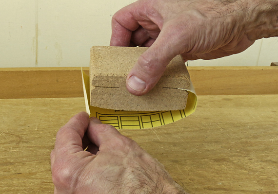
The harder “Hard” felt is available only in sheets without the PSA backing. I cut the 1/8″-thick, 12″ x 12″ sheets into strips and applied them with 3M General Purpose 45 spray adhesive using simple butt joints to make a continuous layer around the wheel. The S2-20 (durometer 50A) works best. The S2-32 (durometer 80A) is nominally about half as compressible as the S2-20 but the difference does not seem to matter for this purpose. I prefer the texture of the S2-20 as it seems to grab the honing compound better.
Because I use the wheel for fine finishing, I charged it with 0.5 micron diamond. Mineral oil-based paste and water-based spray will both work but I think the paste is better. They cut fast but can get expensive over time. An economical alternative is a stick of Formax “green micro fine honing compound,” which I surmise is also about 0.5 micron, available from Woodcraft. Of course, it cannot cut as fast as diamond but with patience it can still produce an excellent edge.
My preference is mineral oil-based synthetic diamond paste from Beta Diamond Products. It cuts fast and consistently, and a little bit goes a long way. I find the jar easier to deal with than the syringe.
Bottom line: the felt replacement works very nicely; I like it a lot better than the leather wheel. It is especially helpful for knives, gouges, and is even handy for quick touch ups of plane blades and chisels. I keep these touch ups very light because I don’t want to round the edge too much, which would interfere the next time I work the edge on stones.