Archive for ◊ April, 2022 ◊

Author:
• Saturday, April 30th, 2022
Record holdfast

The Record #146 holdfast has generated some inquiries over the years, so I’ll address the topic in this post. I bought mine nearly 40 years ago, and while still a good tool, I would not recommend it now because there are better choices. 

I like the Gramercy holdfasts, which I have been using more than the Record for more than 10 years now. They fit in simple 3/4″ holes that you drill directly into the bench top. They cost only $39.95 per pair. I suggest buying the pair because it is helpful to use them together when you want a very secure hold to resist lateral force on the work piece. And you will certainly want more than one of these holes in your bench top because they can be used for many other holding tools, most notably Veritas products including Bench Pups, Wonder Pups, planing stops (I made my own out of wood), and their own holdfast.

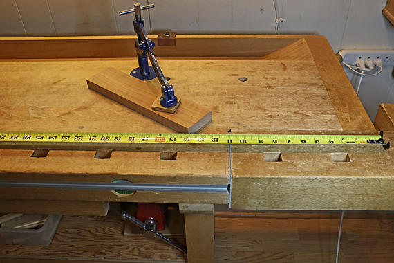
If you do want to use the Record, you have to decide where to place the metal collar that it requires. This collar allows you to place lots of pressure on the work if you need it, making this the strongest holdfast I’ve seen. The collar is not really too obtrusive (I don’t recall having rammed a cutting edge into it) but it would not be there if I was setting up a bench now. Happily, I installed only one, those many years ago, and the location has worked out well. 

This collar placement allows a work piece to be held where I can chop dovetails over the right leg structure of the bench. It also can work in conjunction with the tail vise and dog system on the right side of the bench. The pad of the holdfast reaches close enough to the front and to the right side of the bench for practical purposes, and still extends about two feet from the right edge of the bench.

Record holdfast placement
Category: Tools and Shop  | Comments off
Author:
• Saturday, April 30th, 2022
Hammer A3-31 infeed adjustment bolts

Lots of information can be found on this website about jointer-planer combination machines and the Hammer A3-31 in particular. I have received many inquiries, especially regarding setup and adjustment of the Hammer. One thing that I have not covered in detail is how to make the infeed and outfeed tables parallel to each other along their lengths. This is quite doable but not simple. 

Let us first set the context. As described in detail here, there are several logical steps to adjusting the jointer. In summary:

1. Start by verifying the flatness of the tables.

2. The width of the outfeed table is then made parallel to the cutterblock

3. The arc of the cutting blades must be consistently adjusted relative to the outfeed table. Here is a practical and accurate method applicable to most machines.

And here are the nuts and bolts on the A3-31.

4. The infeed table and outfeed table are then made parallel across their widths by adjusting the infeed table. Step 4 here describes the details, including for the Hammer. 

5. And now for the tricky part. The infeed and outfeed tables must be made parallel along their lengths.

For reasons similar to wanting a hand jointer plane to have a flat sole, so should the machine tables be adjusted. In my opinion, this adjustment should be done with a one-sided tolerance. Aim for the tables to be parallel, but a trace of convexity, like the letter “A,” is OK, but there should be no valley, like the letter “V.”

So, how is this done on the A3-31? In those earlier posts, I referred to “geometry” without presenting the details. You could work hit-or-miss to make the adjustment, but with four points of adjustment involved, it would probably be unnerving and cause you to give up, and then tolerate using a poorly adjusted jointer, which will in turn wreak all sorts of ugly havoc on your ensuing work. So, really, it is worth deciphering my geometric method. It works. 

I attached my handwritten notes, made years ago. Click on the little picture below for a full-size version. 

The front-side adjustment bolts are shown in the photo at the top of this post. 

The hinge-side adjustment screws are found under this plate:

Hammer A3-31 back plate

The pencils are pointing to them: 

Hammer A3-31 hinge-side set screws

These bolts must be both be loosened to allow the set screws to move: 

Hammer A3-31 hinge-side bolts

The method starts with placing a straightedge to extend the full length of the infeed table with a sufficient amount to also have a good register on the outfeed table. The infeed table starts low and then is adjusted upward to the first touch on the straight edge. If you have done all the previous work as described above, the place of the touch will tell you how the tables are aligned. In my machine, the tables were delivered tilted toward each other, like a “V,” so the first touch of the straightedge was at the outer end of the infeed table.  

Measure the gap as shown in my notes. Note then that I have simply diagrammed similar triangles among the straightedge-table and the pairs of adjustment screws, and calculated the amount of adjustment to be made at the appropriate screws. I then converted that into how much to turn each screw based on the thread pitch. 

OK, I think you can see why I did not include this in my original set of posts! It is a bit painful. I like math so I admit to a bit of joy in working this out, but for those A3-31 owners not so disposed, contact me and I’ll try to help. 

Thankfully, the machine holds its adjustments very well.