Archive for ◊ May, 2017 ◊

Author:
• Wednesday, May 31st, 2017

Tormek SE-77

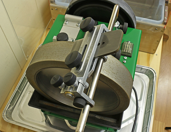
For those not familiar with the Tormek grinder, the SE-77 jig, an upgrade over the older SVH-60, holds the blade and slides onto the guide bar, where it rotates to present the blade edge to the grindstone in a very consistent manner. The niftiest features of the SE-77 are its ability to reliably put a controlled amount of camber on a plane blade, and to microadjust the lateral angle of the blade edge to the stone.

The SE-77 has a sturdy build. The left clamp screw slides to adjust the width between the two clamp screws. This more securely holds a wide range of blade widths. There is an end stop on the right side that squarely registers the right side of the blade into the jig, which is useful for blades with parallel sides.

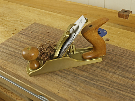
The pair of small thumbscrews, shown in the foreground of the photo below, controls the two special functions of the jig.

Tormek SE-77

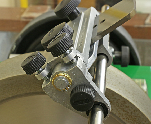
To microadjust the lateral angle of the blade edge against the stone, you back off one of the screws and advance the other the same amount. This is much more reliable than shifting and reclamping the blade in the jig.

To camber the blade edge, you loosen both microadjust screws. This creates a pendulum motion about the small stem. (See the photo: the small stem has a brass washer and external snap ring on its end.) With this pendulum motion, you can guide a controlled amount of camber onto the blade edge. The system works very well, though you do have to blend a gradual arc. A too-heavy touch can create a shallow V-point edge instead of a nice smooth camber.

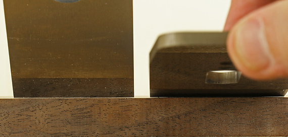
Another welcome feature of the SE-77 is the design of the lower jaw of the blade clamp, which gives a good grip on Japanese chisels (hallelujah!), even onto the shank.

At $66, the SE-77 is not cheap. Having used the Tormek for a many years for grinding – very little on the leather honing wheel – this new jig has been a worthwhile upgrade.

Dear readers, I hope this series on blade camber has been helpful. As always, what I write is born of “the sawdust and shavings of my shop.” These are the techniques and approaches that work for me as I make things. I welcome your ideas and comments.

Rob

Category: Techniques  | Tags:  | 6 Comments
Author:
• Wednesday, May 31st, 2017

skewing effect

Creating the camber

There doesn’t have to be high art in producing the camber. On a coarse diamond stone, I start by leaning the blade to the left and slightly raising the right side. It is important not to overdo this. I then gradually reduce the lean, keeping aware of the approximate number of strokes, and blend the camber through the middle. Then I repeat this on the opposite side.

On the Tormek grinder with the older SVH-60 blade holder, I would lean on the slightly flexible guide bar to create some camber. The newer SE-77, which I will cover in the next post, is more controlled. The camber can be refined on a medium stone. Mild camber, such as in a high-angle, bevel-down smoother, can also be refined when honing the secondary bevel.

It is easy to underestimate the amount of camber by just looking at it without a straightedge reference, so I check the camber by holding a small, wide aluminum square (straightedge) against the edge and observe it against mild backlighting. Eventually, one can reliably relate the appearance to the performance on wood. Again, I do not measure it, nor recommend that as a habit.

cambered plane iron

If you overdo the camber, the nose of the blade will dull first, so when you go back to the stones to clean up the secondary bevel, some of the camber will automatically be reduced.

Skewing the plane

Skewing the plane at a typical angle used routinely has no significant effect on the camber function. However, an extreme skew angle, such as the 45° shown in the top photo, or even 60°, can occasionally be used to advantage to get the plane to pull a shaving from an isolated area, such as to correct a bit of tearout.

This is really just playing with how the plane sole bears on the surface contour of the board. The full camber depth is retained but is effectively spread over a shorter length of blade. (The plane stroke is still about parallel to the length of the board.) With some trial and error, you may be able to get the blade to “reach down” into a localized area.

Camber the chipbreaker too?

Very small differences, on the order of .1mm/.004″, in the setback of the chipbreaker may affect planing performance, at least according to this Japanese experiment. Should the chipbreaker therefore have a camber that matches the blade to create a consistent setback? With a straight-edged chipbreaker on a cambered blade, is there a difference in the shaving characteristic or wood surface across the width of the blade that cannot be explained by the difference in shaving thickness?

In theory, maybe so, but I have only rarely encountered advice to camber the chipbreaker. It also seems like too much trouble, so I don’t do it. Maybe it would help for a highly tuned smoothing plane. Any ideas, readers?

chip breaker setting

Next: the Tormek SE-77 jig

Category: Techniques  | Tags:  | 2 Comments
Author:
• Wednesday, May 31st, 2017

plane iron camber

To master handplanes, a woodworker must master the matter of blade camber. To introduce the bevel-up/bevel-down/frog angle issue, please refer to my 2009 post. Here I want to present a more intuitive approach to guide you at the sharpening bench.

The issue

When checking the blade after grinding, you naturally hold it up and observe the camber, sighting at 90° to the face of the blade, like this. But when the blade sits on the frog at an angle, the effective amount of camber is reduced. Think of it this way: if the cambered blade were laid flat, there would be effectively no camber at all.

So, you have to create what looks like more camber than you need, and just how much more depends on the bed angle.

Please note that I am not suggesting that you take out a leaf gauge and measure the camber! I took measurements for these posts and other writing but that is not my method in the shop. I suggest use the guidelines set out in part one of this series, work intuitively, using a bit of trial and error, and get a sense of how the camber that you see performs on the wood.

As an example, in the photo at the top, with the blades standing vertically, the blade on the left shows about .004″ camber, and the one on the right about .14″. In the photo below, the blade on the left is set at 45° and the blade on the right is set at 12°. This results in an effective camber of about .003″ for both of them.

plane iron camber

So, to get the same effective camber, we had to grind an additional approximately 1/3 more (observed) camber for the blade bedded at 45°, but for the blade bedded at 12°, we had to grind almost five times more (observed) camber.

Here is a handy table to help absorb a general sense of the differences.

Bed angle       Grind this multiple more camber than what the plane needs

12°                 4.81 [whoa, must grind lots more to get what you want]

20°                 2.92

22°                 2.66

45°                 1.41 [grind just a little more than what you want]

50°                 1.31

55°                 1.22

60°                 1.15 [what you see is just about what you get]

And another thing

Camber is somewhat of a nuisance to grind into the blade edge. It slows down grinding and, especially, honing. Unfortunately, and, I contend, for little or no good reason, almost all bevel-up planes made today have a 12° bed. That requires you grind a lot more camber than in a bevel-down plane. If the bevel-up plane had a 22° bed, this problem would be greatly reduced.

This is yet another reason why I continue to advocate that bevel-up planes should be made at about 22°. I explored the matter several years ago in this post and elsewhere.

Skip this part if you want

For those who like this sort of thing (as I do), here is the derivation of the chart above. The key point is that it is a non-linear function because of the sine curve. So, there is a big difference between 12° and 22°, and much less difference between 50° and 60°.

Please refer to the diagram in the 2009 post, which shows how the camber that you observe when your line of sight is 90° to the face of the plane blade is reduced by the sine of the bed angle when the blade is placed in the plane.

f = functional camber with blade in plane

c = observed camber normal to blade

A = bed angle of blade


f = c · sin A

c = f/sin A


c/f = (f/sin A)/f

= 1/sin A

=sin-1 A

The ratio c/f means how many times greater must the observed camber be to produce a given functional camber. c/f is just the inverse of the sine of the bed angle.

Category: Techniques  | Tags:  | Comments off