To master handplanes, a woodworker must master the matter of blade camber. To introduce the bevel-up/bevel-down/frog angle issue, please refer to my 2009 post. Here I want to present a more intuitive approach to guide you at the sharpening bench.
The issue
When checking the blade after grinding, you naturally hold it up and observe the camber, sighting at 90° to the face of the blade, like this. But when the blade sits on the frog at an angle, the effective amount of camber is reduced. Think of it this way: if the cambered blade were laid flat, there would be effectively no camber at all.
So, you have to create what looks like more camber than you need, and just how much more depends on the bed angle.
Please note that I am not suggesting that you take out a leaf gauge and measure the camber! I took measurements for these posts and other writing but that is not my method in the shop. I suggest use the guidelines set out in part one of this series, work intuitively, using a bit of trial and error, and get a sense of how the camber that you see performs on the wood.
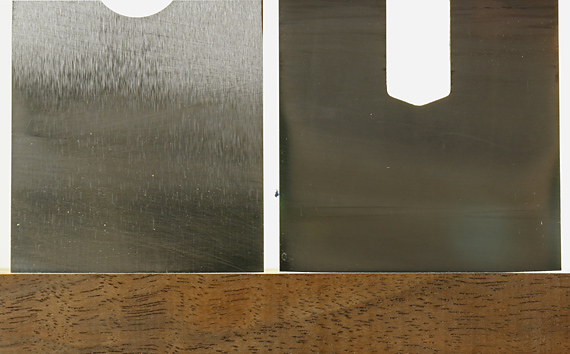
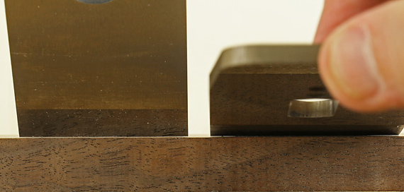
As an example, in the photo at the top, with the blades standing vertically, the blade on the left shows about .004″ camber, and the one on the right about .14″. In the photo below, the blade on the left is set at 45° and the blade on the right is set at 12°. This results in an effective camber of about .003″ for both of them.
So, to get the same effective camber, we had to grind an additional approximately 1/3 more (observed) camber for the blade bedded at 45°, but for the blade bedded at 12°, we had to grind almost five times more (observed) camber.
Here is a handy table to help absorb a general sense of the differences.
Bed angle Grind this multiple more camber than what the plane needs
12° 4.81 [whoa, must grind lots more to get what you want]
20° 2.92
22° 2.66
45° 1.41 [grind just a little more than what you want]
50° 1.31
55° 1.22
60° 1.15 [what you see is just about what you get]
And another thing
Camber is somewhat of a nuisance to grind into the blade edge. It slows down grinding and, especially, honing. Unfortunately, and, I contend, for little or no good reason, almost all bevel-up planes made today have a 12° bed. That requires you grind a lot more camber than in a bevel-down plane. If the bevel-up plane had a 22° bed, this problem would be greatly reduced.
This is yet another reason why I continue to advocate that bevel-up planes should be made at about 22°. I explored the matter several years ago in this post and elsewhere.
Skip this part if you want
For those who like this sort of thing (as I do), here is the derivation of the chart above. The key point is that it is a non-linear function because of the sine curve. So, there is a big difference between 12° and 22°, and much less difference between 50° and 60°.
Please refer to the diagram in the 2009 post, which shows how the camber that you observe when your line of sight is 90° to the face of the plane blade is reduced by the sine of the bed angle when the blade is placed in the plane.
f = functional camber with blade in plane
c = observed camber normal to blade
A = bed angle of blade
f = c · sin A
c = f/sin A
c/f = (f/sin A)/f
= 1/sin A
=sin-1 A
The ratio c/f means how many times greater must the observed camber be to produce a given functional camber. c/f is just the inverse of the sine of the bed angle.
