Archive for ◊ March, 2011 ◊

Author:
• Wednesday, March 23rd, 2011

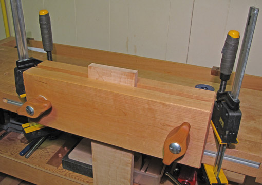
For sawing dovetails, as well as various other tasks, this vise raises the work piece to a more comfortable height than does the typical bench front vise. It was first described by Joseph Moxon, the seventeenth century author of The Art of Joinery. Credit for its revival and refinement goes to Chris Schwarz, editor of Popular Woodworking, who published a modern adaptation of Moxon’s text along with extensive new analysis. Chris published plans for a vise in the December 2010 PW. Stephen Shepherd’s insights and the variations produced by web authors such as Derek Cohen have added to our shared knowledge. What a wonderful example of the vibrancy of current woodworking!

That said, I’ll toss in my two cents: I built my version of the vise and would like to share it with readers.

I used an 8/4 cherry board that had been hanging around the shop far too long and $22 of hardware available locally. The vise jaws are 1 3/4″ thick, 6″ high, and 19 1/4″ wide, with a clamping capacity of 14 1/8″ between the bolts. The ½” diameter 8″ carriage bolts are set in functionally shaped handles. Each is secured with a cross pin (finishing nail) passing through a hole drilled in the shaft of the bolt. The handle shape facilitates a one finger spin of the lightly waxed bolt as well as a solid grip to sock the jaws tight. Clamping thickness capacity is at least 2 ½”.

In the front jaw, for smooth operation and to protect the wood, each bolt is supported in a ½” ID, 3/4″ OD, 1 1/8″ long oiled bronze bushing which sits in a stepped hole. To prevent erosion of the bushing, the first 1 1/2″ of the bolt threads is filled with epoxy and the sharp edges of the threads were eased with a file. A 1/4″ thick, ½” ID, 1 5/8″ OD nylon washer, sanded flat, placed between the handle and the front jaw, protects the wood.
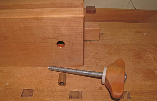
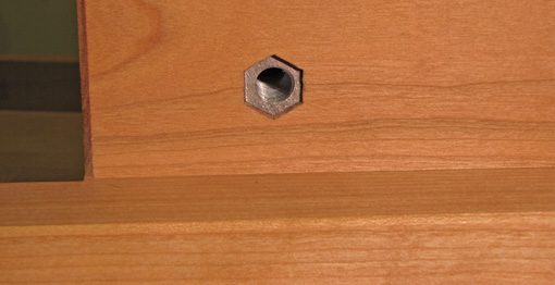
To receive the bolt in the rear jaw, a 2″ long coupling nut was hacksawed to about 1 3/16″ and set from the back side into a stepped hole chiseled to a matching hexagon. This gives more support than a regular hex nut. A wood screw that meets it from the side prevents any chance of the nut twisting in its housing.
The rear cleat, about 1 3/4″ square in section, extends to each side 2 1/4″ beyond the jaws and allows for convenient clamping to the bench. Thanks to Derek Cohen for this idea. I chamfered the edges and finished the wood with one coat of oil-varnish.

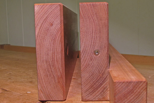
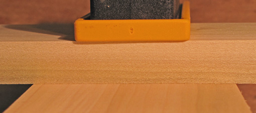
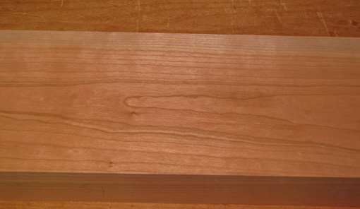
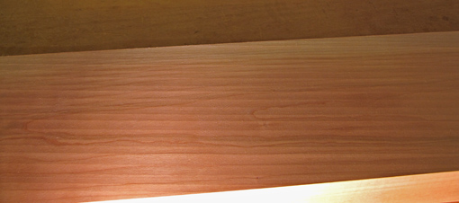
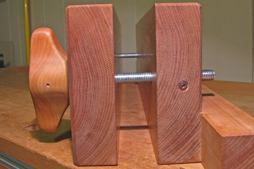
One more detail. Quartersawn wood would have been ideal but I used flatsawn wood because that is all I had available in this thickness. It will inevitably cup and reverse through the seasons. I wanted to avoid a vise that in some seasons would grip the wood only at the central part of the jaw faces and thus make the work piece prone to slipping. I arranged the growth rings as shown in the first photo below and not like the photo beneath it.

Here’s why. I built the vise during the approximate midrange of the yearly humidity cycle in my shop. I left the inner surface of each jaw very slightly concave across its width. As the driest months come along, the inner surface of the front jaw will become more concave while the mating surface of the rear jaw will become flat, then slightly convex. Thus, the grip will be maintained at the limits of the width of the jaws. As the humid months come along, the rear jaw’s inner surface will become more concave (than now) while that of the front jaw will become flat, then slightly convex, again maintaining a good grip of the work piece. Too punctilious you say? Well, the pieces were going to be given some arrangement and I preferred giving it some thought rather than just guessing, and this is one simple solution.
 

The vise now has had test runs in the shop and I like it a lot. It feels more ergonomic for use with a Western dovetail saw than with a Japanese saw due to differences in the handle angles, but it is good for both.

Author:
• Thursday, March 17th, 2011

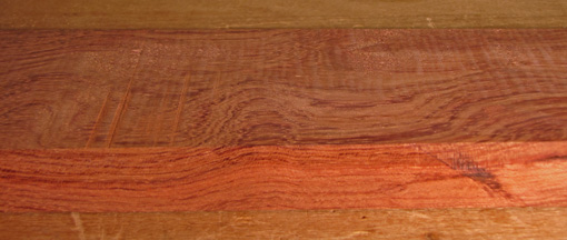
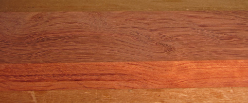
The nasty waterfall bubinga in the top photo, above, shows the clean, tearout-free surface produced by the Shelix, while the lower photo shows ugly tearout, visible toward the far edge of the board, from a conventional cutterhead. This is the great advantage of the Shelix for the work I do.

But how does the scalloped surface – see the previous post – left by the Shelix fare in the building process?

First, assessing this surface for flat and square is not a problem. True, if you hold a straightedge across the wood and back light it, you can see tiny gaps created by the valleys of the scallops. However, the straightedge (or square, or winding stick) sits on the peaks of the scallops and permits an adequately accurate evaluation.

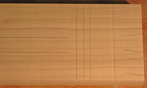
For marking out, I wondered if lines would look squiggly. Again, no problem. I marked with a fine pencil point across and along the grain, laid out dovetails, and knifed lines across the grain (and made a “V” shoulder on one of them). See below: the markout looks fine to me and would be easy to follow with a saw or to chop against.

How about glue lines? Just as with a conventional cutterhead, I would not use a Shelix surface for edge gluing. (Anyway, the Shelix is on my planer, not the jointer.) I always hand plane the machined surface to increase accuracy and the quality of the glue surface. No machine can remove a thousandth of an inch in a controlled manner and leave behind a pristine, unbattered surface the way a hand plane can.

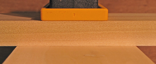
However, for bent laminations I want to glue directly from the machined surface and I do not own a thickness sander. I have not tried this yet with the Shelix but I think urea formaldehyde glue such as Unibond 800 or URAC 185, which I use for laminating, would easily fill the tiny voids created by the scallops. These are barely noticeable in the photo directly below which shows the meeting of two crossgrain Shelix surfaces. For comparison, the photo below that shows the meeting of two handplaned surfaces.

Maybe there will be times when I don’t want that scalloped surface but I doubt it will be often, especially as I get more used to the Shelix. I still have my Inca 10″ jointer-planer but will probably use it only as a jointer for the vast majority of work.

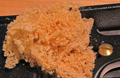
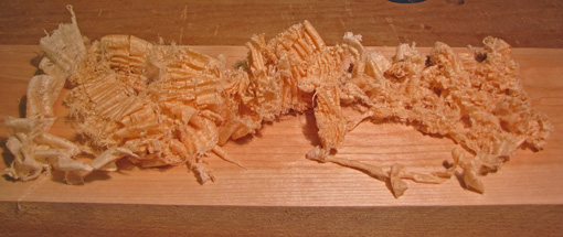
Well, when it comes time to clean up the Shelix-machined surface, how goes it? Wonderfully! This is an unexpected advantage of the Shelix. When hand planing, the peaks of the scallops register the sole of the plane and stringy shavings are first created. The shavings widen as the valleys are approached and finally planed away. So, for figured species it is actually easier to avoid tearout when handplaning (or scraping) the Shelix surface compared to a conventionally machined surface. Furthermore, the gradual removal of the peaks makes it easy to evenly plane the width and length of a board because the shavings indicate your incremental progress and tell you when you are done. It is somewhat like cleaning up a toothed plane surface.

The shavings first look like this:

This photo shows, from right to left, the progression of shavings:

With all this in mind, I think for most projects, I will be able to hand plane away the scalloped surface, or partially clean it up, at the same point in building that I would for a conventional machined surface, and when I do clean it up, it will go very well. For example, to dovetail a box, I would clean up the inside surfaces, mark and cut the dovetails, glue up, then plane the outside surfaces.

While it truly takes a long time and varied circumstances to fully assess the value of a tool, I think I’m on board with this thing. I’m especially more confident dealing with figured woods.

[This review is uncompensated and I have no relationship with Byrd Tool.]

Author:
• Sunday, March 13th, 2011

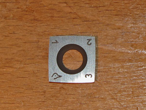
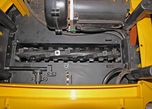
The Shelix employs three helical rows of 11 carbide cutters, arranged so that each cutter’s path is partially overlapped by other cutters. The edge of each cutter is slightly cambered (actual width of the cutter pictured above is about 5/8″) and meets the wood at an angle to the axis of the cutterhead (see below) for a shearing cut, much like skewing a handplane. Each cutter can be rotated three times to use a fresh edge when, after a long time, one has dulled. This is very different from 13 inches of blade meeting the wood all at once.

So, how does the Shelix perform? In short, beautifully. However, it produces important differences in the wood surface compared to a standard cutterhead.

The first thing I tested was the consistency of thicknessing across the width of the bed. I passed two 3/4″ wide wood strips simultaneously through the planer at each side of the bed. They came out less than 0.001″ different from each other in thickness. Wow.

The planer seems to vibrate slightly more with the Shelix but this does not seem to get translated to the bed or the wood. Noise is reduced – still loud enough for hearing protection, but not the scream produced with the OEM blades. Planing wide stock demonstrated that the Shelix gives the DW735 significantly more functional power. Dust collection improved from excellent to great, with fewer shavings sticking to the rubber rollers.

I fed this beast some nasty woods, including waterfall bubinga, curly and quilted maple, lacewood, rowed mahogany, and brittle curly pear. I took passes that I expected to be too deep and fed some wood in the wrong grain direction. The results: no tearout! The only exception was very slight on the lacewood (which hates machine blade surfacing) but much less than with the OEM blades. It laughed at the docile, straight-grained cherry in the photo below.

So, where’s the “but . . . ?” Look at the photo below, showing the same cherry board as above, but in a low, raking light. Notice the scalloped rows produced by the cambered cutters. The depth of the scallops is about 0.002″. This is different from what we’re used to with machined surfaces.

I thought at first that the scalloped surface would be a disadvantage. I wondered if referencing off such a surface would be compromised. Obviously, any machined surface is not the final one for furniture, but I wondered how this surface would clean up, and at what point in a project I would start to do so. More intriguing, could the scalloped surface have any advantages? All of these questions must be addressed to be able to integrate this new tool into the process of a woodworking project.

Next: answers to the above.

Author:
• Monday, March 07th, 2011

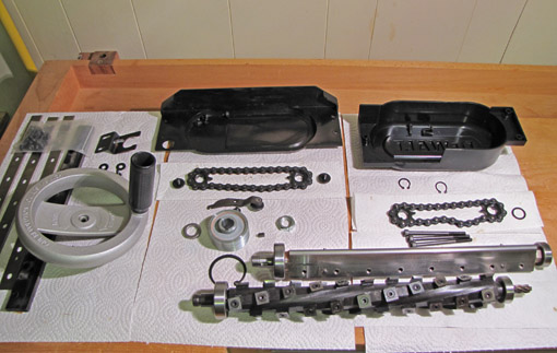
The Byrd Tool website has outstanding illustrated step-by-step instructions for the DW735. The photo above shows the parts laid out after the OEM cutterhead was removed. It is without its blades just behind the Shelix in the photo above.

Referring to those instructions, here are a few helpful tips:

  • Step 4. The cutterhead lock cannot be reinstalled with the Shelix which does not have a flat on its shaft.
  • Step 10. Also remove the rocker tensioning arm (it is removed in the second photo in Step 11).
  • Step 11. It is difficult to remove and reinstall the nut on the end of the head. It seems to be about 22mm  is a 23 mm hex (per report from a reader, see comments) for which I do not have a socket head. I used a locking pliers on the nut and gripped the pulley with grip gloves.
  • Steps 13 and 15. You need a snap ring tool for this installation. The small external snap rings in step 15 are delicate.
  • Step 14. There are 3 screws on that cover, not 4.
  • Step 22. Removing the helical gear from the OEM cutterhead is very difficult. The ridiculously tiny hexhead is very hard to grip, and it quickly gets rounded. Locking pliers finally worked. The same goes for reinstalling the helical gear on the Shelix. In order to tighten it, I needed a helper with heavy gloves to grasp the cutterhead which I wrapped in layers of cloth. Yes, it is standard right-hand thread, in case, like me, you have doubts when trying to remove it from the DW head.
  • Step 24. The supplied plastic cover sheet helps a lot but cut it a few inches narrower.
  • Step 25. The bearings fit VERY tightly in their housings. Lots of pounding with a dead blow hammer is necessary to seat them.

Next: the Shelix design and its performance in the shop.

Author:
• Monday, March 07th, 2011


I have had my eye on carbide segmented cutterheads for a while. After studying the options and particularly after reading Glen Huey’s excellent article in the February 2011 Popular Woodworking, I decided to get the Byrd Shelix cutterhead for my DeWalt DW735 planer.

Most of my pieces use highly figured woods. I had been having trouble getting good surfaces from the planer on some of these difficult gems of nature, despite using appropriate technique. I don’t expect a machine planer to yield a finished surface, of course, but tearout surprises can require corrective handwork sufficient to change dimensions and relationships. Parts meant to match and reference surfaces were disturbed; there was too much backtracking and unpredictability. This affected my work flow and was frustrating.

In considering a segmented cutterhead, I first had to decide if the DeWalt DW735 was a good enough machine in which to invest. After years of use, its design, quality, and reliability are proven. So, primarily for the joy of using my beloved figured woods, I took the plunge: $447 for a Byrd Tool Shelix – “she” for shear, and “helix”. (Sounds like a part to soup up a motorcycle or something.)

Below is the Shelix in all its medieval-looking glory. Thankfully, it comes with the bearings attached

In future posts, I will discuss the basic design and performance of the Shelix, and how this tool is integrated into the work flow of a project. The latter issue is the most important one and required the most thought to make this a sensible investment.

The post immediately following this one lists tips for installing the cutterhead.