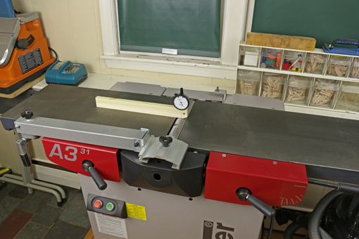
After the posts on jointer-planer combination machines and the Hammer A3-31, some readers emailed questions about how to align the tables and knives so the jointer does what it is supposed to do – produce flat, straight surfaces on wood.
Here are the steps in tuning jointer tables and knives. The methods of adjustment will, of course, depend on the make and model of your machine, but hopefully this will clarify the overall logic of the process. Methods specific to the A3-31 are entered within brackets.
1. The cutterhead rotates on its axis. This is the reference to which all the other parts must be aligned.
Further, the tables should be flat. Of course, they are not perfect but if they are pretty good – not dished/bumped/twisted more than a few thou – then go with what you have. Some localized imperfections will cancel out with the procedures described here. In any case, practical woodworking, not perfection, is the goal.
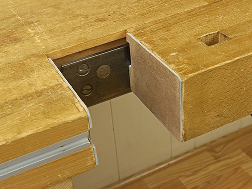
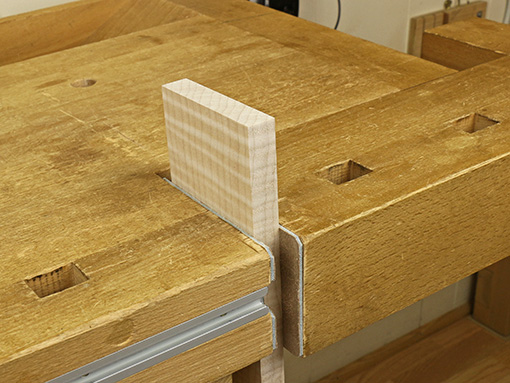
2. Check the parallelism of the cutterhead block to the outfeed table. This step is often neglected. Make a wooden holder for a dial indicator as shown in the photo. Alternatively, a feeler gauge and the stock of a square can be used but this is awkward.
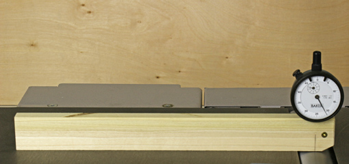
The reading is noted when the tip of the indicator is at the top of the cutterhead circle (i.e. its most retracted reading) at several points across the width. Use the same portion of the circumference of the cutterhead for all of the readings to negate any imperfections in the roundness of the cutterhead.
If the indicator readings are not consistent across the width, the tilt of the outfeed table on its long axis must be adjusted to make it parallel with the cutterhead. My outfeed table is parallel to the cutterhead within half a thou across the full width.
[On the A3-31, the two M12 x 1.75 bolts on the handle side under the outfeed table are adjusted. Calculate the amount of turn required and work from there rather than guessing. You should not have to adjust from the hinge side for this.] Other jointers may require shimming where the table and base castings meet on one side.
3. Adjust the height of the outfeed table relative to the knife arc. The knife arc should be consistent for all three blades and all across the cutterhead. On most jointers, this is adjusted by means of jackscrews in the blade holder. Really you are making the knife arcs consistent with the cutterhead, which previously has been determined to be parallel with the outfeed table. Aim for the top of the knife arc to be a thou or two above the infeed outfeed table using the method described in this post.
Hopefully, you are in the range of requiring only small adjustments of a few of the jackscrews. However, if it is way off for all of the knives, the outfeed table should be adjusted as a unit. [For the A3-31, this latter adjustment is found under the left side red plate. Page 33 of the User Manual shows where it is and how to move it.]
At this point, you should have a cutterblock parallel to the outfeed table, three knife arcs also parallel to the outfeed table, and the top of the arcs should be about .001 – .002” above the outfeed table. Only now should you turn your attention to the infeed table.
Note that wear of the knife edges may later require very slight adjustment in the overall height of the outfeed table. However, the parallelism should be retained.
4. Make the infeed table parallel to the outfeed table across their widths. Assess this just at the cutterhead-end of the infeed table. Use the dial indicator jig or place a 12” straightedge on the outfeed table and extend it past the cutterhead just an inch or two over the infeed table.
Adjust the infeed table using the regular depth-of-cut lever to about the shallowest cut. Observe the dial indicator or use a feeler gauge under the straightedge to check across the width of the infeed table for parallelism of the tables. If the tables are out of parallel, it is easiest to retain the outfeed table settings and adjust the tilt of only the infeed table along its long axis.
[On the A3-31, adjust the two M12x1.75 bolts on the handle side under the infeed table. Again, calculate the amount needed and work from there rather than guessing.] Other jointers may require shimming where the table and base castings meet on one side
5. Finally, adjust the infeed table so the infeed table and the outfeed table are parallel along their lengths. Assess this with the longest, best straightedge that you can find. You do not want the tables tipped in toward each other at all (like a V), in my opinion. You want them parallel or, if anything, a trace tipped away from each other (like an A).
It is easiest to retain the outfeed table settings and make the adjustment only on the infeed table. It is tilted on its short axis only by making equal adjustments on both sides of the table so as not to disturb what was accomplished in step 4. Again, the specifics will vary among machines. The intent here is to explain the overall logic.
[To adjust this on the A3-31 you have to work on both sides of the infeed table. On the near side are the M12x1.75 bolts. On the hinge side there are M10x1.5 set screws, accessed under the plate cover. To make a directed adjustment, rather than by trial and error, there is some geometry required. The Hammer manual does not cover this. I’ve done the geometry and it works but to write and diagram it is beyond the intent of this post. Hey Hammer, how about updating that 2005 manual to reflect the current model machine!]
The object of all of this is to get the machine to produce surfaces within the tolerances you need for the work you want to do. That is the answer to the question of how precise these adjustments need to be. Practical woodworking, not perfection, is the goal.