Archive for the Category ◊ Tools and Shop ◊

Author:
• Friday, March 13th, 2015

Mini Gorilla dust collector

My small shop requires making efficient use of every bit of floor, wall, and air space, including for dust collection. The setup described here has proven convenient and effective.

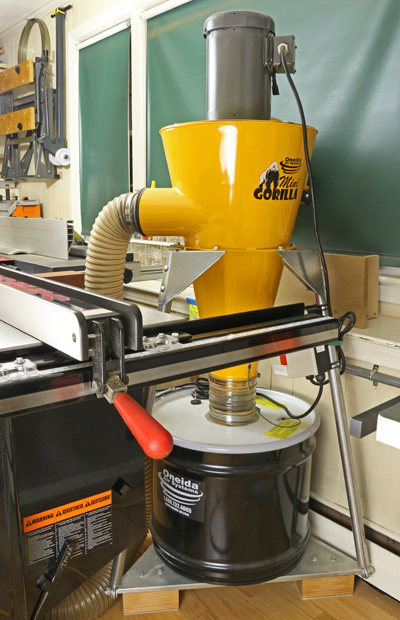
The Oneida Mini Gorilla is set on the “mobile” stand but since it will not be moved, I took off the wheels and attached wooden blocks under the platform (see photo above) to save a little space and make the assembly more stable. The whole thing is tucked away just to the right of the table saw, with the filter facing mostly away from the interior of the shop.

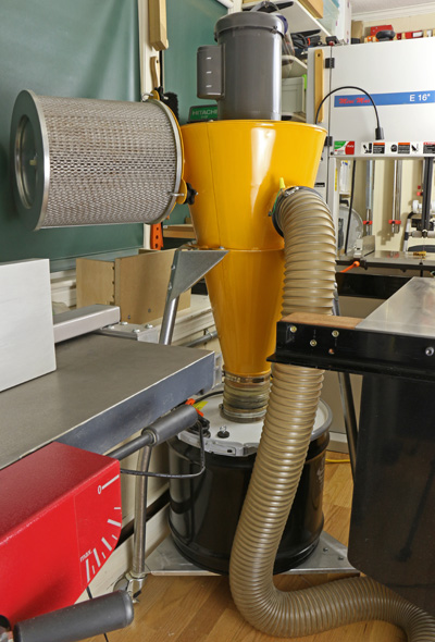
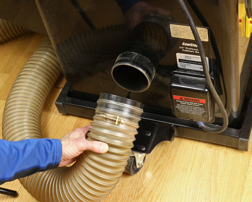
Using a 5″-4″ reducer, I attached a 4″ flexible plastic-wire hose to intake port of the collector. This type of hose, available from Rockler, Woodcraft, etc., is durable and easy to handle. A 5″ hose seems more awkward to handle and the 4″ certainly handles all of the chip production from my machines, as discussed in the previous post. It also meets the requirement specified by the manufacturer for airflow through the filter.

Mini Gorilla dust collector

I simply bring the hose to each machine as needed, which is very quick to do. The default location is attached to the table saw and with some of its length curled under the saw’s motor hood. Each machine – table saw, bandsaw, jointer-planer, router table – and a dust hood accepts a simple press-fit plastic female connector that is attached to the end of the hose. The ports on some of the machines required modifications for the hose connector to fit uniformly on all of them.

Mini Gorilla dust collector

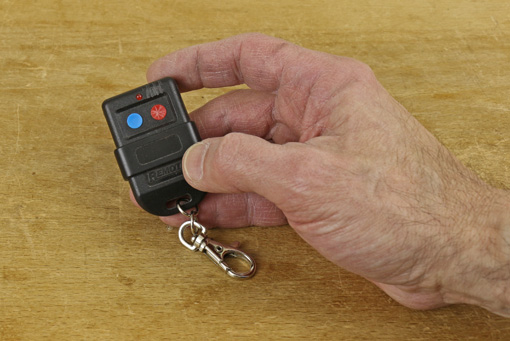
The remote control is very handy, almost a must. It works by radio frequency, not infrared, so no optical line of sight is required.

Mini Gorilla dust collector

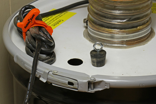
The steel collection drum holds 17 gallons. I empty it into a 45-gallon trash bag, which makes the job easy. Smaller trash bags made the job considerably more difficult. It is fairly tight quarters getting the drum off and back on the machine but not a big deal. I would have bought the super deluxe infinite capacity drum at an untold price but, um, I was told these have been banned because they defy the laws of physics.

The Mini Gorilla can also be ordered from Oneida with a wall mount bracket. This would not have worked out in my shop but you may want to consider it. It allows the use of a 17, 35, or 55-gallon drum, while the mobile stand is limited to the 17-gallon drum.

Now the steel drum is, of course, opaque, and if you let it fill up such that dust gets backed up higher into the system, you will have a very unpleasant time cleaning the pleated HEPA filter. I made this mistake – twice!

A drum level sensor is available from Oneida but my solution was to drill a hole (approximately 1″ in diameter) in the lid and block it with a rubber stopper with a screw eye handle. When my guardian angel taps on my shoulder, I check on the bin by removing the stopper and peering in with a flashlight or just inserting a rolled up piece of paper or dowel as a depth gauge. It works.

Mini Gorilla dust collector

The Mini Gorilla motor can be wired as 110V/16A or 230V/8A. I run mine on a 110V/20A circuit with a dedicated outlet. Keep in mind the collector draws a lot of juice and there will always be another machine running with it, so check your electrical capacity and outlets.

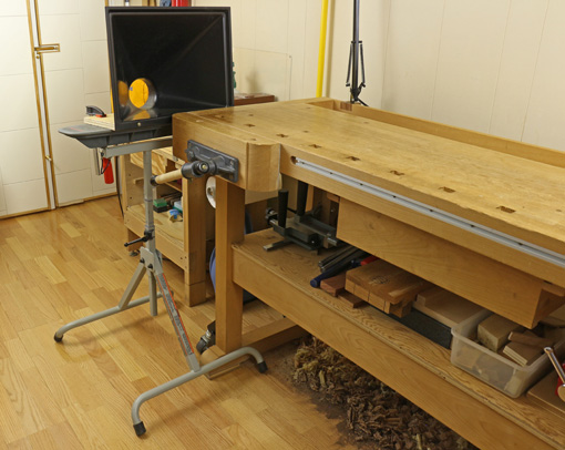
The dust hood shown below clamped to an outfeed stand is helpful at various locations, especially for the storm of debris produced by router mortising with an upcut spiral bit. By the way, the shavings under the bench are just fine for a while where they are, without a dust collector.

dust collection hood

Category: Tools and Shop  | 3 Comments
Author:
• Thursday, March 12th, 2015

Mini Gorilla dust collector

For many years, dust collection in my shop had been the basic bag-over-bag single-stage collector familiar to most of us small shop woodworkers. A few years ago I upgraded to the Oneida Mini Gorilla, a cyclone collector, and it has been excellent. I’ve received many inquiries about it from woodworkers considering upgrading their dust collection system, so I hope this report will be helpful.

A cyclone collector is more efficient that a single stage collector because it involves two stages of collection based on particle size. Here’s what happens. The impeller fan whips around the intake material in the big sheet metal cone that give these machines their characteristic appearance. The chips and larger dust particles that constitute almost the entire volume of the intake fall into the collection drum below the cone.

Thus, only the finest dust – the most unhealthful – gets passed on to the air filter, the cage-like cylinder sticking out the side of the yellow cone in the photo above. This permits the use of an incredibly efficient sub-micron pleated HEPA filter without it getting continually overburdened and clogged with debris.

What all this means is that my shop is cleaner, and more important, healthier.

The Mini Gorilla easily handles the biggest producers of chips in my shop, the Hammer A3-31 12″ jointer-planer and the DeWalt DW735 planer. The only limitation is the dust gathering efficiency at the source. Fortunately, the A3-31 and DW735 are great in this regard. The Minimax bandsaw is good while the Saw Stop table saw (vintage 2005) is just fair.

Oneida rates the noise produced by this machine at 76dB(A) at 10 feet. As a practical matter, it seems noisier than what I remember of the old bag-on-bag collector but it’s not bad and certainly not a deal breaker. The Mini Gorilla is very space-efficient – notice the motor on top of the cone – so its footprint is smaller than most small single-stage collectors.

It’s not cheap. The base price is now $780, according to Oneida’s website. A mobile stand or wall bracket, steel drum, and shipping push the total over $1 large.

Oneida’s website has details about the Mini Gorilla and the rest of their large line of dust collectors. This review is unsolicited and uncompensated.

Grunt machines like a good dust collector are not glamorous and there is a natural reluctance to invest in them. However, I think they support a sense of freedom in the shop because they take good care of the dirty work and produce a better working environment. That freedom, in turn, produces more creativity, which is what this is all about.

Next: How I set up the Mini Gorilla in my small shop.

Author:
• Saturday, January 31st, 2015

wood floor

If you are working in a shop with a concrete floor, such as in a basement, consider installing a wood floor. It may be easier than you think.

If you are working in the garage, consider coming indoors and using your hard-earned living space for what really matters to you. For example, banish the TV set to an obscure corner somewhere.

A wood floor is easier on your feet and back. It is also much kinder to a dropped tool, especially an edge tool. The wood floor dampens sound so it’s easier on your ears, and it certainly is a whole lot easier on your eyes. You’ll feel better in a shop with a wood floor and enjoy your time there more. Take it from someone who spent too long here:

concrete floor

Consider a floating installation of engineered flooring. The material is basically plywood topped with a thick ply of beautiful hardwood of your choice, pre-finished with a very heavy duty finish. It comes in strips about 5″ to 7 1/2″ wide, which can contain multiple sections across the width, as seen in my floor in the top photo. The planks are attached to each other but not to the floor below, upon which they simply sit. The planks connect to each other with tongue and groove plus glue, or with a super easy “click lock” connection without glue.

Not tough enough for a workshop? I can tell you my experience. Twelve years ago, I installed an engineered floating red oak floor over concrete in my workshop, which is a few feet below grade. It has held up very well, including no cracks and no separation of the planks, with 600-pound machinery rolling over it, big planks of hardwoods dragged over it, sawdust, dropped tools, and so forth.

I do note that the finish of the particular brand that I installed was later assessed to be more susceptible to denting but it is minor, and the floor still looks great. I also find the finish rather slippery, though this has diminished over time, so I would also keep that issue in mind when choosing material. Ask the experts, let them know you are putting the floor in your workshop, and consider the denting and slippery issues.

Installation involves first, a simple moisture test. Then the concrete floor will probably need to be leveled with leveling compound. Next, a heavy poly plastic sheet is laid down and a thin foam sheet goes on top of that. Then the floor is laid down. Finally, molding and thresholds are installed. The biggest issues are strategies to facilitate laying the flooring, such as starting from the correct side of the room, baseboard heating appliances, and so forth.

You can do this; you’re a woodworker for goodness’ sake.

You do, however, need professional advice. Here in eastern Massachusetts, Hosking Hardwood is well-known (you may recall them from their appearances on the “This Old House” PBS TV series), has an informative website, and offers expert advice.

Category: Tools and Shop  | 4 Comments
Author:
• Saturday, January 31st, 2015

tail vise liner

The jaws of the traditional tail vise on my old Ulmia workbench seem to the eye to meet accurately but there must be a minute misalignment because in use the grab on the work piece was slightly inconsistent across the full area of the bare jaw surfaces. Paring or scraping tiny corrections on the end grain surfaces of the jaws would have been difficult if not impossible to get right.

Then too, the opposite faces of the work piece not being precisely parallel may also cause an imperfect grip. And the smooth end grain of hardwood does not have much gripping power anyway.

The solution is to line the jaws with material that is firm but with a just bit of give to compensate for such those slight misalignments. It should also be somewhat grippy but not too much, which would prevent adjusting the work piece position when the vise is partially loosened.

I’ve tried various liners such as thin rubbery material and cork but there is no equal to leather – real leather. Cowhide lace leather works very well. This is tough, firm leather, almost 1/8″ thick (thick enough to make laces). Here is one source.

lace leather

lace leather

I applied it with Nexabond 2500M CA glue, rough side out. A little experimenting showed that the rough side grips better than the smooth side, though surprisingly there is not much difference. The rough surface does not seem to make impressions even in soft species like poplar.

The tail vise now has a monster grip. Yet backing off the pressure on the vise makes it easy to reposition the work piece, such as when adjusting the angle when sawing tenons.

tail vise

Category: Tools and Shop  | 4 Comments
Author:
• Saturday, January 31st, 2015

bench blanket

As the parts of a project approach completion, dings and scrapes are increasingly interrupting and protection becomes a greater issue. For relaxed efficiency it sometimes helps to cover the workbench or assembly bench with cushiony material during glue ups or other work toward the end of a project.

Over the years, I’ve tried various materials with mixed success:

Velour fabric and felt work fairly well. These are inexpensive and widely available in 54″ widths. Downsides of fabrics are the tendency to hold sawdust and small wood chips, and soak up glue drips.

Router mats are another option but their grip and open weave are not always desirable. Mover’s blankets (try Harbor Freight) are economical and cushion very well but are actually too mushy for my liking. Wood parts do not register firmly on the surface and their corners can catch in the soft blanket when you try to slide them.

Finally, I think I’ve found a near perfect solution: upholstery grade bonded leather. Made of shredded real leather and polyurethane, it is the better-looking MDF of the leather industry. It costs about $24 per yard at 54″ wide so you can get a single piece to cover even a large assembly bench.

bonded leather

The top (working) side looks and feels very similar to fine leather and the underside is similar to the rough side of real leather. Just 3/64″ thick, it nevertheless is resilient enough to provide protection for wood parts without being too spongy.  Glue drips can be easily wiped off the surface. It seems like it will be very durable.

The photo at the top shows a piece draped over a 24″ x 48″ sheet of MDF placed on the workbench for assembly work.

This material also makes good clamp pads. Cut it to size and apply it to clamp heads with spray adhesive.

Category: Tools and Shop  | Comments off
Author:
• Wednesday, December 31st, 2014

jointer alignment

After the posts on jointer-planer combination machines and the Hammer A3-31, some readers emailed questions about how to align the tables and knives so the jointer does what it is supposed to do – produce flat, straight surfaces on wood.

Here are the steps in tuning jointer tables and knives. The methods of adjustment will, of course, depend on the make and model of your machine, but hopefully this will clarify the overall logic of the process. Methods specific to the A3-31 are entered within brackets.

1. The cutterhead rotates on its axis. This is the reference to which all the other parts must be aligned.

Further, the tables should be flat. Of course, they are not perfect but if they are pretty good – not dished/bumped/twisted more than a few thou – then go with what you have. Some localized imperfections will cancel out with the procedures described here. In any case, practical woodworking, not perfection, is the goal.

2. Check the parallelism of the cutterhead block to the outfeed table. This step is often neglected. Make a wooden holder for a dial indicator as shown in the photo. Alternatively, a feeler gauge and the stock of a square can be used but this is awkward.

jointer alignment

The reading is noted when the tip of the indicator is at the top of the cutterhead circle (i.e. its most retracted reading) at several points across the width. Use the same portion of the circumference of the cutterhead for all of the readings to negate any imperfections in the roundness of the cutterhead.

If the indicator readings are not consistent across the width, the tilt of the outfeed table on its long axis must be adjusted to make it parallel with the cutterhead. My outfeed table is parallel to the cutterhead within half a thou across the full width.

[On the A3-31, the two M12 x 1.75 bolts on the handle side under the outfeed table are adjusted. Calculate the amount of turn required and work from there rather than guessing. You should not have to adjust from the hinge side for this.] Other jointers may require shimming where the table and base castings meet on one side.

3. Adjust the height of the outfeed table relative to the knife arc. The knife arc should be consistent for all three blades and all across the cutterhead. On most jointers, this is adjusted by means of jackscrews in the blade holder. Really you are making the knife arcs consistent with the cutterhead, which previously has been determined to be parallel with the outfeed table. Aim for the top of the knife arc to be a thou or two above the infeed outfeed table using the method described in this post.

Hopefully, you are in the range of requiring only small adjustments of a few of the jackscrews. However, if it is way off for all of the knives, the outfeed table should be adjusted as a unit. [For the A3-31, this latter adjustment is found under the left side red plate. Page 33 of the User Manual shows where it is and how to move it.]

At this point, you should have a cutterblock parallel to the outfeed table, three knife arcs also parallel to the outfeed table, and the top of the arcs should be about .001 – .002” above the outfeed table. Only now should you turn your attention to the infeed table.

Note that wear of the knife edges may later require very slight adjustment in the overall height of the outfeed table. However, the parallelism should be retained.

4. Make the infeed table parallel to the outfeed table across their widths. Assess this just at the cutterhead-end of the infeed table. Use the dial indicator jig or place a 12” straightedge on the outfeed table and extend it past the cutterhead just an inch or two over the infeed table.

Adjust the infeed table using the regular depth-of-cut lever to about the shallowest cut. Observe the dial indicator or use a feeler gauge under the straightedge to check across the width of the infeed table for parallelism of the tables. If the tables are out of parallel, it is easiest to retain the outfeed table settings and adjust the tilt of only the infeed table along its long axis.

[On the A3-31, adjust the two M12x1.75 bolts on the handle side under the infeed table. Again, calculate the amount needed and work from there rather than guessing.] Other jointers may require shimming where the table and base castings meet on one side

5. Finally, adjust the infeed table so the infeed table and the outfeed table are parallel along their lengths. Assess this with the longest, best straightedge that you can find. You do not want the tables tipped in toward each other at all (like a V), in my opinion. You want them parallel or, if anything, a trace tipped away from each other (like an A).

It is easiest to retain the outfeed table settings and make the adjustment only on the infeed table. It is tilted on its short axis only by making equal adjustments on both sides of the table so as not to disturb what was accomplished in step 4. Again, the specifics will vary among machines. The intent here is to explain the overall logic.

[To adjust this on the A3-31 you have to work on both sides of the infeed table. On the near side are the M12x1.75 bolts. On the hinge side there are M10x1.5 set screws, accessed under the plate cover. To make a directed adjustment, rather than by trial and error, there is some geometry required. The Hammer manual does not cover this. I’ve done the geometry and it works but to write and diagram it is beyond the intent of this post. Hey Hammer, how about updating that 2005 manual to reflect the current model machine!]

The object of all of this is to get the machine to produce surfaces within the tolerances you need for the work you want to do. That is the answer to the question of how precise these adjustments need to be. Practical woodworking, not perfection, is the goal.

Author:
• Thursday, December 25th, 2014

diamond nagura

In previous posts, I discussed nagura stones in general and presented a rationale for a diamond nagura. Here is a report on the development of a diamond nagura.

Pictured above on the right is a makeshift first attempt produced by cutting down a DMT 1200 diamond stone. The polka dot surface reduces sticking to the finishing stone but improvement is needed.

The other two naguras were made by routing 5/32″ wide x 1/16″ deep channels in 1″-thick ABS plastic, sawing out 2″ square blocks, and applying PSA diamond sheet to the prominent surfaces. The one on the left is 300 grit and the middle one is 1200 grit.

These channeled diamond naguras work much faster that any other nagura I have used and sticking is completely eliminated. The square pattern of channels allows the user to intuitively retain slurry on the stone or sweep some of it away to produce the desired surface ready for sharpening.

So, returning to the rationale for a nagura, at least two definite nagura functions are expedited: the improvement in “feel and ride” of the blade on the finishing stone with the slurry, and “refreshing” the surface of the stone by removing metal and glazing. Removal of defects on natural stones and perhaps even some localized flattening are also facilitated.

Several questions remain:

1. Does the slurry actually cut steel? I don’t know for sure but the slurry and the action of the nagura are still useful for the other reasons stated.

2. Does the diamond nagura crush the grit particles released from the finishing stone to produce finer particles that cut steel either in the slurry or lodged in the stone surface or both? The lodging effect can be somewhat likened to powdered silicon carbide lodging into a steel flattening plate (kanaban).

3. If that is so, does a 1200 grit nagura crush better and produce finer particles than coarser grits do? As I have mentioned in the past, my sense is that the crushing is real, enhances sharpening, and is indeed better with 1200 than with coarser grits.

In any case, the 1200 diamond nagura test model feels much more friendly on the finishing stone than does the 300 version, which feels too scratchy and harsh.

4. Are diamond particles breaking free from the nagura and thus becoming available to score heavy scratches in the tool? A sharpening stone expert alerted me to this possibility with 1200 grit diamond. So far, I have not noticed this in testing with the 1200 model but I did feel it once using the 300, though the latter diamond film is lower quality.

I wonder if DMT’s “Hardcoat Technology,” which they use on their 95 micron/160 mesh diamond Lapping Plate, could be applied to 1200 grit to safeguard against this potential problem.

In summary, progress has been made but there is more work to do.

Category: Tools and Shop  | Tags:  | One Comment
Author:
• Monday, December 22nd, 2014

Naniwa Chosera 10,000

I still think the Naniwa Chosera 10,000 is a great finishing stone for all the reasons discussed in an earlier post but unfortunately it developed a large crack across the lower area after drying from a sharpening session. Fortunately, the loose area cleanly separated with a light tap with a chisel. I epoxied it in place with System Three T-88 and flattened both faces. The top face is uninterrupted and the stone works fine.

Naniwa Chosera 10,000

So what happened?

Over months of using the stone, I had gravitated to a soaking time of 15 minutes before use, though never longer. Searching the internet produces different recommendations from knowledgeable dealers and users: 15 minutes, at least 10 minutes, 5-10 minutes, no longer than 5 minutes, and some suggest no soaking at all. Everyone agrees that the magnesia binder, which contributes to the excellent feel of these stones in use, will not withstand prolonged soaking. There is also no doubt that the stone should be allowed to air dry slowly and evenly, which I did consistently. There are reports online of hairline cracks and major splits like the one in my stone.

The stone certainly absorbs water and so does not work as nicely in a splash-and-go mode as does a Shapton. As a practical matter, I found that soaking it for, say, 5 minutes is not much better than not soaking at all – it still pretty quickly drinks in the little puddle of water placed on it. This happens a bit slower after a brief presoak but also slows down during the sharpening session even without a presoak.

So, to play it safe and practical, I no longer presoak the stone. I just puddle some water on the surface and work from there, adjusting as necessary. This works out just fine. It’s still a very cool stone to sharpen on and produces excellent results, but I just wanted to give readers a heads up on the potential for cracking and how I chose to deal with it.

By the way, Naniwa now sells the Chosera line as the “Professional Series.”