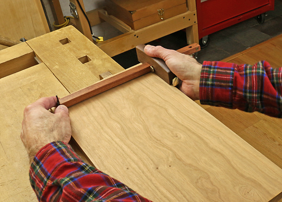
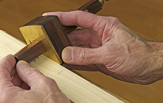
Unlike the almost all of the cutting and marking gauges discussed in the previous four installments of this series of posts, mortise gauges generally do not have either scribing point at the end of the stem. To gain better visibility of the marking action, I prefer to push a mortise gauge.
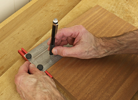
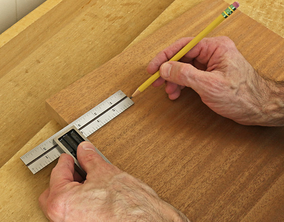
In use, tilt the gauge to make the marking action smoother and to prevent the points from jumping and creating errant marks. Control the angle and pressure based on the hardness of the wood and the desired depth of the mark. Consider supporting the far end of the stem depending on the resistance of the wood. Marking out is important so take a moment to clamp the work and do it right.
Points, knives, and sorta knives
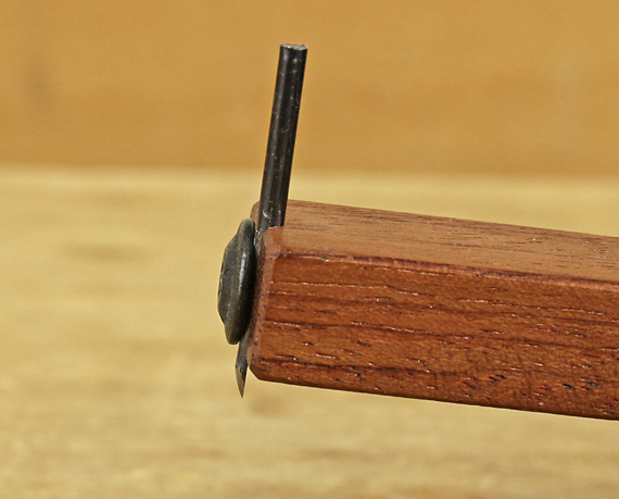
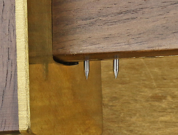
Because a mortise gauge is used along the grain and on end grain, I prefer simple conical points, mostly because I can see its mark better but also to keep things simple and consistent. Some gauges employ half-conical points that are sharpened like tiny knives. I find their marks harder to see.
One type of Japanese mortise gauge employs two L-shaped actual knives, which makes the marking action easy to see, but I find those knife lines hard to see and follow. I do not like knives in a mortise gauge.
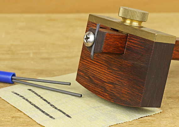
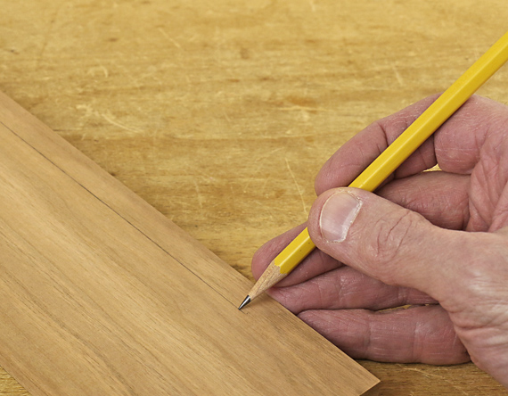
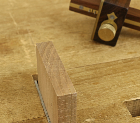
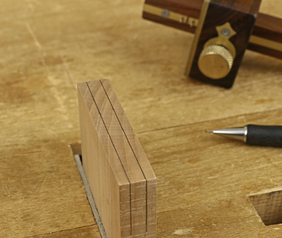
The marks made by conical points, which are actually V-shaped grooves, are easy to fill in with a pencil to further improve their visibility. Here is a refinement that you might want to experiment with (but is hard to photograph). Run a relatively blunt pencil in the groove such that the walls, but not the full depth of the groove, receive the lead, effectively creating two separate but very closely spaced pencil lines. Saw to make one line in the keeper wood and the other in the waste.
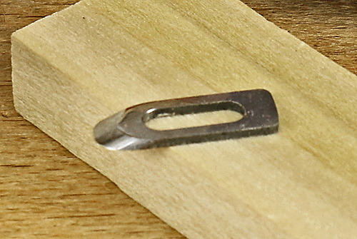
Preference in the type of markers will depend on how you do mortise and tenon work. Tiny knife points (sharpened half-cones) with the bevels facing each other may have a marginal advantage over conical points for setting the gauge to a mortise chisel and laying out the mortise with the bevels in the waste.
I almost always machine mortises. The flats of the tiny knives, which are facing outward, can be accurately set against the mortise walls and the spacing transferred to the tenon piece. But then the bevels are in the keeper wood, which I feel diminishes sawing accuracy.
Ugh, too complicated! The conical points are simple, consistent, and what I recommend. I can accurately set them to a routed mortise by widening the gap between the points to where they just barely no longer fit into the mortise slot. Then I aggressively attack the resultant layout lines when sawing the tenon by hand. The points can be similarly gapped to the width of a mortise chisel by looking for zero to trace clearance of the pins across the chisel. Keep the same setting for the tenon and saw to the layout aggressively.
Also note that filing the 1/16″ diameter conical points that are on most mortise gauges into half-conical tiny knives may weaken them too much.
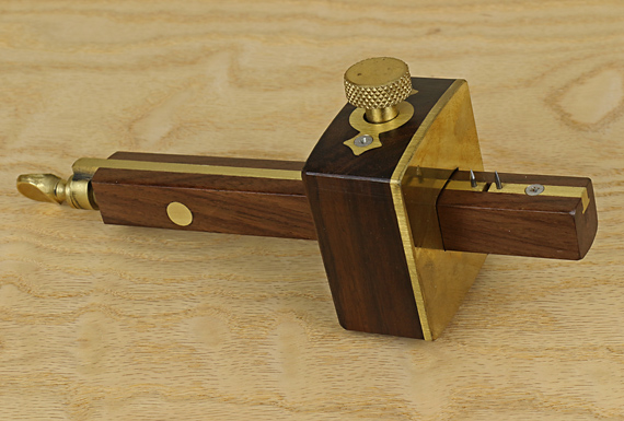
Marples deluxe gauge
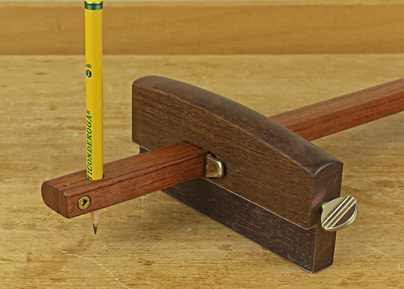
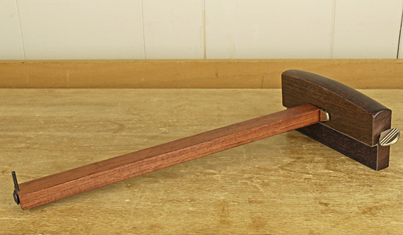
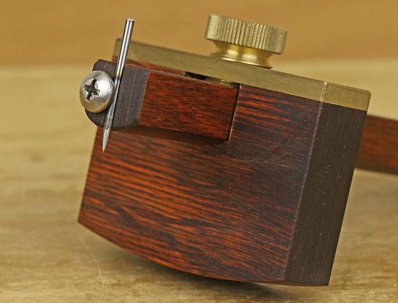
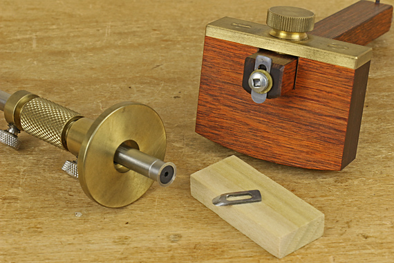
I am mostly happy with my Marples deluxe gauge, pictured here. It has a full brass fence face and nice heft. The screw-feed adjustment is, I feel, far easier to set than the slide adjustment on some mortise gauges.
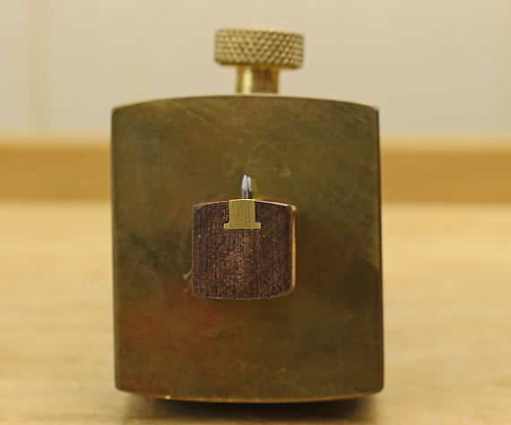
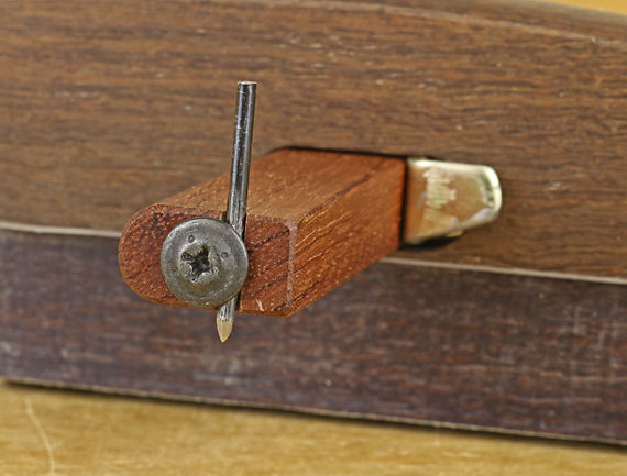
Look at how far off vertical the clamping screw is. Sloppy or intentional? [Tool vendors: any comments?] Though this does not seem to be present in the photos of the gauge on vendors sites, I hope it is intentional because the slightly angled screw presses (via a brass wear pad) off-center on the top surface of the stem, which is radiused. This shoves the stem into the opposite lower corner of the fence mortise, beautifully preventing any wobble of the stem. One alternative to prevent wobble might be to shim the fence mortise.
Tuning points
In tuning your mortise gauge, the point tips should enter the wood at same level with the fence held snugly against an accurately squared work piece. This will produce two marked lines of the same depth. In theory, the stem has to be perpendicular to the fence face (in the plane of the marking points) for this to happen at all extension positions of the points. If it is not square, and it probably is off a bit as is mine, just set the gauge in the most common position that you use it and file the points into true for that position. It does not have to be perfect.
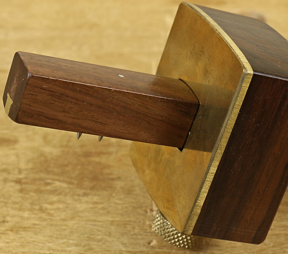
Oh, and how about that annoying, useless third spur on the opposite side of the stem? I have never used it. As I write these posts, I think through my habits and rationales for doing things the way I do. So, I finally got around to grinding off that point.
That’s all for this series of five posts on gauges. Hard to believe I had 3,000 words to say on the topic but I have tried to keep the discussion beyond the basics that are churned out in most sources. Thanks for reading and I hope this helps your woodworking.