Archive for the Category ◊ Tools and Shop ◊

Author:
• Monday, July 31st, 2017

small woodworking shop

Here’s a question just for fun. In the past 30-40 years, which advance in tooling has made the biggest practical change in small shop furniture making? An individual tool, a type of tool, or a major upgrade in a tool category, hand or power, all qualify.

The answer will depend on the definition of “small shop.” What I have in mind is what I most relate to, which is the one-person shop making high-end furniture and accessories. Such a shop produces one-of-a-kind pieces or very few repeats, and may be an amateur at home, or a professional, whose furniture making is only part of his income.

OK, with that in mind, drum roll . . . my vote is for the Ryobi AP-10 portable thickness planer, which was first made in about 1985 or 1986, as best I recall. This humble machine, which I owned back then, was the first lightweight, portable, low-cost way to easily and quickly thickness large quantities of wood. The Ryobi begot improved competing models, such as the much later DeWalt DW735.

For the small production shop, I am guessing CNC, along with CAD, has made the biggest difference. For shops of any size, the overall improvement and proliferation of carbide-tipped tooling – router and shaper bits, table saw blades, bandsaw blades, jointer/planer cutters, etc. – may be the biggest advance.

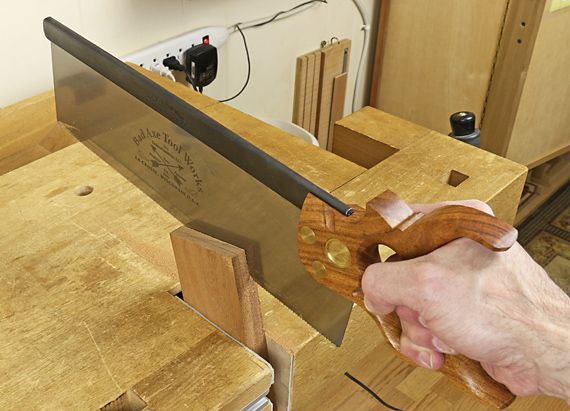
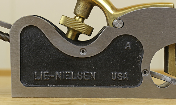
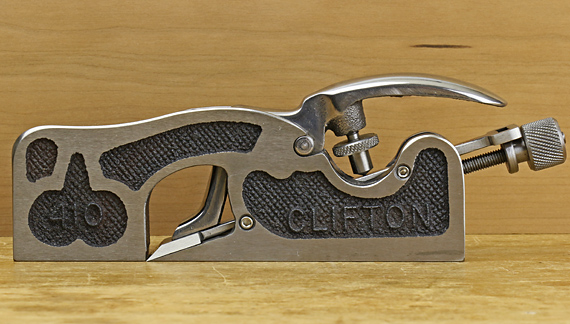
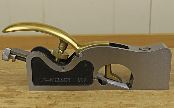
To impart the touch of quality that is only possible with hand tools, we must, of course, acknowledge the roles of first, Lie-Nielsen, and then, Lee Valley/Veritas. More than with vintage tools, new Mercedes-quality handplanes became readily available and indeed, the standard, which elevated everyone’s work. As a tool category, this may be the most significant advance. The same evolution occurred in Western hand saws, culminating, in my opinion, in the Bad Axe line.

Other tool categories that came to mind in thinking about this include: greatly improved tool batteries for cordless tools, the wider availability of high quality steel-frame bandsaws sized for the small shop, the wider availability of wide over-under jointer-planers, and the availability of excellent Japanese hand tools. For individual tools, the biscuit joiner, Saw Stop table saws, and Japanese waterstones deserve some notice but I would not consider these pivotal.

Oh, and there is one more “tool” that, come to think of it, probably has made the biggest difference of all: information! Books, magazine, video/Internet, classes, and so forth have tremendously advanced the joy of good woodworking.

It’s all good. We are fortunate.

Category: Tools and Shop  | 8 Comments
Author:
• Friday, March 31st, 2017

Bad Axe tenon saw

Years ago, Japanese saws were the staples of my saw armamentarium. They offered very good quality and value.

However, another big reason for using them was to save myself the trouble of maintenance. The replaceable blades, especially those by Gyokucho and Z brand are of remarkably consistent and high quality, especially for their prices. Back then, alternatives were to rehabilitate vintage saws, or try to soup up a new, but low quality, Western saw.

Times have changed.

The renaissance of saw making that started in the US in the 1990s with Pete Taran and Patrick Leach’s Independence Tool Company (since folded) was followed by several fine saw makers producing at artisan volumes. Equally important, more sources of excellent information became available to help us with understanding, using, and maintaining Western handsaws.

At the head of the class, in my opinion, is Bad Axe Tool Works. Their combination of quality, performance, and range of options exceed any maker in the world today. If you read this blog much, you know that I am not given to overstatement. I also have had the opportunity to try out saws from a substantial majority of the artisan makers around today. I use Bad Axe saws.

I have seen Mark Harrell and his crew work their apparent magic in his Wisconsin shop, making, sharpening, and fixing saws, and I can tell you that it is no magic at all. They simply work with incredible care from an awesome base of knowledge and skill.

Now, back to the saw maintenance issue. Mark has made that a much more accessible job by producing solid, clearly written information on saw sharpening, repair, and restoration. Short of visiting his shop, please see the trove of instructional information available on the BATW site. It will elevate your skills and understanding tremendously.

First-rate tools, knowledge, and skills – that’s what we want. Times have indeed changed in woodworking.

Category: Tools and Shop  | 7 Comments
Author:
• Monday, March 13th, 2017

Ulmia auxiliary vise #1812

Ulmia used to produce this auxiliary vise, model #1812. I first saw it many years ago on page 145 of my copy of the 1977 hardcover Van Nostrand Reinhold edition of The Fine Art of Cabinetmaking, where the author, James Krenov, commented that it is “well made and very useful.”

I wish I bought one before Ulmia discontinued production. I have tried with some success to use a modified small drill-press vise, a shop-made wooden vise, and handscrews to gain some of the functionality of the Ulmia. Still, I coveted a real #1812 hilfs-spannstock.

About three years after posting the above links, and missing out on Ebay in the meantime, someone from Germany contacted me to offer a new-old-stock #1812. I jumped at it and have since found it to be every bit as useful as I had anticipated.

The vise jaws are 2 3/8″ x 1″. The fixed jaw is further from the knob, while the other jaw moves on a 9/16″-diameter, acme-threaded screw feed to produce a maximum opening of 2 1/8″. The wooden base is 5 3/4″ x 3 1/4″ x 2 1/2″. The vise is surprisingly beefy for its size.

Ulmia auxiliary vise #1812

The hole in the base makes it convenient to clamp to the bench top, as shown in the top photo, for a wide variety of small-scale tasks. With the #1812 held recessed in the tail vise, as in the photo just above, the jaw still travels freely. You can adjust the protrusion of the jaws above the bench surface to keep them out of the way while planing or paring small work pieces.

It would be good to have this very useful tool back in production. I wonder if Ulmia would consider making it again, or, depending on patent restrictions, if another toolmaker, such as Veritas, would be interested in producing it. I am sure that woodworkers who would own one would turn to it often, as I do.

Category: Tools and Shop  | 10 Comments
Author:
• Sunday, January 29th, 2017

set screws added to Lie-Nielsen shoulder plane

Since I cannot have my dream shoulder plane with all of the nifty features discussed in the previous post, an easy, helpful modification to my shoulder planes was in order: set screws in the style of the Veritas shoulder plane.

First, I marked the blade position on the sides of the body, and within that, locations for the screws on flat areas. I drilled and tapped for #8-32 screws (#29 drill for 75% thread). On the Lie-Nielsen large shoulder plane, above, I ground the socket end of 1/4″-long screws to shorten them to 7/32″ because 3/16″-long screws were barely long enough for all situations.

The 11/16″ x 5 5/16″ Clifton 410, below, which I have owned since before Lie-Nielsen made their similarly sized shoulder plane, is shown below with the set screws added. The 18° bed is sufficiently resistant to deflection, on par with the L-N.

Clifton shoulder plane modified

On the Clifton, there is less room to fit the #8-32 screws into flat areas on the body, so I put the higher pair of screws to the rear of the lever cap wheel. They barely cleared the blade bed there, so it probably would have been better to instead put screws forward of the wheel where there is no blade bed to interfere. #6-32 screws would probably have been easier to install but the #8-32 x 3/16″ screws work well as they are.

In use, I have been finding it easiest to approximately set the lateral position and angle of the blade with the lever cap lightly clamped. Then I adjust the lower two screws, one on each side, to barely meet the blade. The screws themselves can then be used to fine-tune the blade position. Next, I advance the two higher screws to barely touch the blade. Then I adjust the cutting depth and snug the lever cap wheel. Note that the set screws may need to be backed off, just a trace, to adjust the cutting depth.

The set screws have proven to be helpful in setting and maintaining the blade position in these shoulder planes.

Category: Tools and Shop  | One Comment
Author:
• Friday, January 27th, 2017

Lie-Nielsen shoulder plane modified

In considering features of all-metal shoulder planes, I will say at the outset that I am not entirely happy with any that I have owned or tried out. Later, I will explain a partial remedy.

Let’s look at some of the key features of planes from the two major players, Veritas and Lie-Nielsen. Spoiler alert: there’s a deal killer coming.

1- The blade adjustment knob of the Veritas controls both the depth and angle of the cutting edge. This is handier than the single function depth adjuster on the L-N.

2- Both planes have an excellent adjustable mouth but, like many vintage infill shoulder planes, the Veritas’ is set significantly further back from the front of the plane than is the Lie-Nielsen mouth. I find the longer initial registration of the sole on the work makes it easier to work accurately.

3- The Veritas has a special hole in the body and knobs that some woodworkers may find helpful in gripping the plane. I tend to like fewer of such grip aids on tools, and find that the L-N handles just as well as the Veritas.

4- The Veritas plane uniquely has four set screws in the body that make it easier to set and maintain the blade alignment. Shoulder planes are finicky to adjust; the screws really help.

5- Both planes are made from stress-relieved ductile iron to the wonderfully precise standards that woodworkers gratefully expect from these two great companies. We can count on receiving a plane with a good 90° angle between the sole and both sides. The blades come well prepared and are of excellent steel. As for the small matter of looks, I do not really care, but if there was a shoulder plane beauty contest, let’s just say that the Veritas has a shot at Most Congenial.

Why, then, do I own a L-N and not a Veritas shoulder plane? Because Veritas has, for me, a real Deal Killer.

The Veritas blade is bedded at 15°. This scant support makes the sole too sensitive to downward deflection beneath the blade. Working with the medium size Veritas, I found that the deflection is quite variable with even small changes of torque on the lever cap wheel. Lee Valley instructs that while little clamping pressure is required, the deflection itself can be used to tune the cutting depth. My interpretation of this is that the lever cap pressure is assigned two purposes, which may be at odds with each other.

Sure, any plane sole that lacks side support, such as on a shoulder plane, can be made to deflect with enough pressure from the lever cap, but for my money, the Veritas shoulder plane was just too sensitive to this. Though the set screws do indeed help maintain the blade alignment, I found that making the blade reasonably secure involves creating an annoying bump in the sole.

This bump prevents the plane sole from registering on the work as well as it otherwise might; it rocks. If it is important for the sole of a plane used for precision work to be very flat, say within a thou or so, what sense is there in tolerating a noticeable bump behind the blade?

The 18° bed of the L-N resists deflection much better. This is why, all things considered, I prefer the Lie-Nielsen shoulder plane. Perhaps there are factors in the design of their plane body other than the bed angle that also contribute to this better resistance to deflection. Taking the matter further, maybe a 20° or 22° bed would even better resist deflection, as those are very workable bed angles in general for a bevel-up plane.

Next: an easy modification (yes, you can see it above)

Category: Tools and Shop  | 2 Comments
Author:
• Saturday, January 07th, 2017

mortise gauge

Unlike the almost all of the cutting and marking gauges discussed in the previous four installments of this series of posts, mortise gauges generally do not have either scribing point at the end of the stem. To gain better visibility of the marking action, I prefer to push a mortise gauge.

In use, tilt the gauge to make the marking action smoother and to prevent the points from jumping and creating errant marks. Control the angle and pressure based on the hardness of the wood and the desired depth of the mark. Consider supporting the far end of the stem depending on the resistance of the wood. Marking out is important so take a moment to clamp the work and do it right.

using a mortise gauge

Points, knives, and sorta knives

Because a mortise gauge is used along the grain and on end grain, I prefer simple conical points, mostly because I can see its mark better but also to keep things simple and consistent. Some gauges employ half-conical points that are sharpened like tiny knives. I find their marks harder to see.

mortise gauge points

One type of Japanese mortise gauge employs two L-shaped actual knives, which makes the marking action easy to see, but I find those knife lines hard to see and follow. I do not like knives in a mortise gauge.

The marks made by conical points, which are actually V-shaped grooves, are easy to fill in with a pencil to further improve their visibility. Here is a refinement that you might want to experiment with (but is hard to photograph). Run a relatively blunt pencil in the groove such that the walls, but not the full depth of the groove, receive the lead, effectively creating two separate but very closely spaced pencil lines. Saw to make one line in the keeper wood and the other in the waste.

tenon layout

tenon layout

Preference in the type of markers will depend on how you do mortise and tenon work. Tiny knife points (sharpened half-cones) with the bevels facing each other may have a marginal advantage over conical points for setting the gauge to a mortise chisel and laying out the mortise with the bevels in the waste.

I almost always machine mortises. The flats of the tiny knives, which are facing outward, can be accurately set against the mortise walls and the spacing transferred to the tenon piece. But then the bevels are in the keeper wood, which I feel diminishes sawing accuracy.

Ugh, too complicated! The conical points are simple, consistent, and what I recommend. I can accurately set them to a routed mortise by widening the gap between the points to where they just barely no longer fit into the mortise slot. Then I aggressively attack the resultant layout lines when sawing the tenon by hand. The points can be similarly gapped to the width of a mortise chisel by looking for zero to trace clearance of the pins across the chisel. Keep the same setting for the tenon and saw to the layout aggressively.

Also note that filing the 1/16″ diameter conical points that are on most mortise gauges into half-conical tiny knives may weaken them too much.

Marples deluxe gauge

I am mostly happy with my Marples deluxe gauge, pictured here. It has a full brass fence face and nice heft. The screw-feed adjustment is, I feel, far easier to set than the slide adjustment on some mortise gauges.

Marples mortise gauge

Look at how far off vertical the clamping screw is. Sloppy or intentional? [Tool vendors: any comments?] Though this does not seem to be present in the photos of the gauge on vendors sites, I hope it is intentional because the slightly angled screw presses (via a brass wear pad) off-center on the top surface of the stem, which is radiused. This shoves the stem into the opposite lower corner of the fence mortise, beautifully preventing any wobble of the stem. One alternative to prevent wobble might be to shim the fence mortise.

Tuning points

In tuning your mortise gauge, the point tips should enter the wood at same level with the fence held snugly against an accurately squared work piece. This will produce two marked lines of the same depth. In theory, the stem has to be perpendicular to the fence face (in the plane of the marking points) for this to happen at all extension positions of the points. If it is not square, and it probably is off a bit as is mine, just set the gauge in the most common position that you use it and file the points into true for that position. It does not have to be perfect.

Oh, and how about that annoying, useless third spur on the opposite side of the stem? I have never used it. As I write these posts, I think through my habits and rationales for doing things the way I do. So, I finally got around to grinding off that point.

mortise gauge

That’s all for this series of five posts on gauges. Hard to believe I had 3,000 words to say on the topic but I have tried to keep the discussion beyond the basics that are churned out in most sources. Thanks for reading and I hope this helps your woodworking.

Author:
• Monday, January 02nd, 2017

panel gauge with pencil

Sometimes, directly gauging a pencil line gives all the accuracy you need. Here are some options of various degrees of ease and precision.

Plain old #2

In the wooden stem of most gauges, you can drill a hole, saw a kerf, and locate a tightening screw to bind the walls of the hole around an installed ordinary pencil as I have in my panel gauge, above.

In the case of this panel gauge, the pencil cannot be gripped close enough to its point to allow the step in the fence to ride on the surface of the board. A simple solution is to hold a temporary shim block under the step to keep the stem parallel to the face of the board and the pencil in good contact with the surface.

A pencil holder is available as an option in the large Hamilton gauge.

Naked lead

For a more precise pencil line in smaller scale work, install a 2 mm drafting lead in the little groove that held the conical steel marking point, as described in the previous post. Gently tighten the screw. Now you have a pencil marker at the end of the stem where it is easy to see in action, as discussed in part 1 of this series.

2mm leads in marking gauge

Sharpen the lead to a bevel point on 220-grit, or finer, sandpaper. HB lead with a light touch works well. 2H wears better but leaves a less prominent line.

Incra dinka doo

Incra T-rule

The Incra T-rule easily scribes pencil layout lines to very accurate absolute measurements in 1/64″ increments. Set the point of 0.5mm mechanical pencil lead in the desired hole and simply slide the fence along the edge of the board.

Combo square

Slide the stock of a combination square, large or small, set to the desired length, against the edge of the board as you hold a pencil point against the end of the blade.

square as marking gauge

It is a must to somehow clamp the work piece for these last two methods.

Look, only hands!

Simplest of all, hold a pencil in your hand and stiffen your extra fingers against the edge of the board so they act as a fence as you slide your hand along to mark the line. This is surprisingly accurate and suffices for many tasks.

hand gauge

Use a light touch. Also, beware of the possibility of splinters on a board with a roughsawn edge, especially in species such as wenge or Douglas fir.

As with everything else in woodworking, have a repertoire of tools and methods at your behest, and choose those that effect the ease and precision appropriate for the task. That is much of what is skill is about.

Next: mortise gauges

Author:
• Monday, January 02nd, 2017

panel gauge

These conical and half-conical markers are strictly for use along the grain. There they make a wider groove than a knife point that is easier to see on its own, and easier to fill with a pencil to improve its visibility.

panel gauge

I keep the half-conical marker installed in my panel gauge because it is a bit easier to pull through the wood than a full conical point, and its flat face makes one side of the groove nearly square. For marking out the width of a panel, it is slightly better to orient the flat side of the marker toward the fence (and the keeper wood) and thus the bevel will be in the waste wood.

half-conical point

As a further refinement, you can rotate the point to make the flat face angled slightly away from the fence in the direction of travel of the gauge. This will help pull the fence toward the edge of the board similarly to the Japanese cutting gauge discussed in part 1 of this series. I usually like to pull the panel gauge.

A panel gauge has a stepped fence that keeps the long stem parallel to the face of the board and square across it. However, this prevents you from tilting the fence – and the marking point – as you would with a regular gauge that uses a point marker. Thus, it is all the more helpful that the half-conical point offers less resistance.

To make the fence ride easier, I attached PSA UHMW plastic to the vertical and horizontal working faces. In use, clamp the work piece and use your second hand to support the marking end of the stem so it does not catch and wander.

using a panel gauge

The conical point is handy for general work. It can be ground to a slimmer tapered point to slightly reduce resistance in the wood. These can be made by grinding the shank of a 5/64″ (2mm) drill bit. The half-conical point is more difficult to make and to find. Mine came from a very old gauge.

marking gauge

These marking points can be easily mounted to the end of the wooden stem of most gauges by simply sawing a small kerf and then refining it with a needle rasp. Locate a pan-head screw, or better, a lath screw, so a flat area on the underside of the head sits over the apex of the cylindrical portion of the marking point, thereby gripping it.

As I am demonstrating below with a mortise gauge, tilt a gauge that uses a conical marking point toward the direction of travel to make the marking action smoother. This avoids jumping, digging in, and inaccuracy.

using a mortise gauge

Next: some options for gauging with a pencil

Category: Tools and Shop  | Tags:  | Comments off